
Method for making pole piece and battery cell, and battery core and pole piece for wound battery

A winding type pole piece technology, which is applied in the production of pole pieces and batteries, and in the field of winding battery batteries and pole pieces, can solve the problems of inconvenient outlet of the pole ears, and achieve the convenience of wire outlet and arrangement, and solve the problem of pole pieces. The effect of inconvenient ear access

Active Publication Date: 2018-09-18
CALB CO LTD
View PDF7 Cites 0 Cited by
  • Summary
  • Abstract
  • Description
  • Claims
  • Application Information

AI Technical Summary

Problems solved by technology

[0004] The purpose of the present invention is to provide a pole piece, aiming to solve the problem in the prior art that the pole piece is inconvenient to go out after being wound.

Method used


Image

  • Method for making pole piece and battery cell, and battery core and pole piece for wound battery
  • Method for making pole piece and battery cell, and battery core and pole piece for wound battery
  • Method for making pole piece and battery cell, and battery core and pole piece for wound battery

Examples


Embodiment 1

[0052] Embodiment 1 of the production method of the pole piece in the present invention: the production method of the pole piece in this embodiment is the same as the production method of the positive electrode piece in the foregoing embodiment, so it will not be repeated.

Embodiment 2

[0053] Embodiment 2 of the manufacturing method of the pole piece in the present invention: the manufacturing method of the pole piece in this embodiment is the same as the manufacturing method of the negative electrode piece in the above-mentioned embodiment, so it will not be repeated.

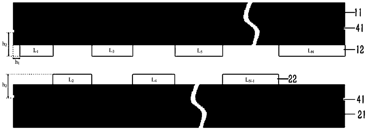
[0054] Embodiment 1 of the pole piece in the present invention: the pole piece in this embodiment is the intermediate product of the above-mentioned manufacturing method of the battery-A positive electrode piece, such as figure 2 As shown, the pole piece includes a band-shaped A-coated area 11. Mark holes 41 are respectively provided at both ends of the A coating area 11, and the Mark holes 41 are used as the start and end points of the pole piece. The coating area is divided into a number of segments from the start point to the end point in sequence, and the length of each segment satisfies the formula: L N =L 0 +N*π*(d 1 +d 2 +2*d 3 )*(1+K), where N: the serial number counted from the beginni...

Embodiment 3

[0060] The third embodiment of the pole piece in the present invention: the difference between this embodiment and the pole piece embodiment 1 is that the pole piece is an A negative electrode piece that is adapted to the A positive electrode piece to be wound into the same cell. Each segment of the coating area of ​​the film satisfies the formula: L N =L 0 +(N-1)*π*(d 1 +d 2 +2*d 3 )*(1+K).


PUM

PropertyMeasurementUnit
thicknessaaaaaaaaaa
lengthaaaaaaaaaa
heightaaaaaaaaaa

Abstract

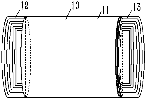
The invention discloses a manufacturing method of a pole piece and an electric core, and the electric core and the pole piece for a winding battery. The coating area of ​​the pole piece is divided into multiple segments in turn from the starting point to the end point, and the length of each segment satisfies the formula: LN=L0+(N‑1)*π*(d1+d2+2*d3)*( 1+K) or LN=L0+N*π*(d1+d2+2*d3)*(1+K), where N: the serial number of the segment counted from the beginning of the coating area, the starting value is 1, L0: the inner circumference of the needle, d1: the thickness of the positive electrode, d2: the thickness of the negative electrode, d3: the thickness of the separator, K: the correction factor; one side of any adjacent segment is provided with the The tab area is formed by a tab with the same length as the segment at the first segment, and a vacant area with the same length as the segment is formed at the other side, and the tab area and the vacant area are located on the same side of the coating area. In this way, after the positive and negative pole pieces are wound into battery cores from the starting point, the lugs of each pole piece will be concentrated on one side of the end face of the battery core in a diameter direction, so that the battery cores can go out from one side of the end face.

Description

Technical field [0001] The invention relates to a pole piece, a manufacturing method of an electric core, and an electric core and an pole piece for a wound battery. Background technique [0002] In recent years, lithium-ion batteries are not only widely used in digital products, but also have made great progress in the field of power batteries. The structure of lithium-ion batteries in the power battery field is currently mainly divided into laminated and wound types. The winding structure of lithium-ion batteries is widely used in most power battery companies because of their relatively high production efficiency. According to the different winding structure, there are mainly two structures: full tab winding and multi tab winding. The full tab structure generally adopts the form of tabs on both sides. Multi tab winding can make the positive and negative The location is designed on the same side to increase the energy density of the battery. In the early production method of ...

Claims


Application Information

Patent Timeline
Patent Type & Authority Patents(China)
IPC IPC(8): H01M4/13H01M2/26H01M4/139H01M10/0587
CPCH01M4/13H01M4/139H01M10/0587H01M50/531Y02E60/10Y02P70/50
Inventor 潘芳芳肖亚洲辛晓冬王栋梁
Owner CALB CO LTD
Learn More