Capacitive coupling structure for metal cavity filter product

A technology of capacitive coupling and metal cavity, which is applied in the direction of waveguide devices, resonators, electrical components, etc., can solve the problem of suppressing strict product consistency and achieve short debugging time, stable performance and easy production Effect

Inactive Publication Date: 2017-01-04
KAELUS COMM EQUIP SHANGHAI
View PDF6 Cites 1 Cited by
  • Summary
  • Abstract
  • Description
  • Claims
  • Application Information

AI Technical Summary

Problems solved by technology

[0006] The purpose of the present invention is to provide a capacitive coupling structure for metal cavity filter products in order to overcome the defects of the above-mentioned prior art, and solve the problem of suppressing the consistency of strict product production

Method used


Image

  • Capacitive coupling structure for metal cavity filter product
  • Capacitive coupling structure for metal cavity filter product

Examples


Embodiment

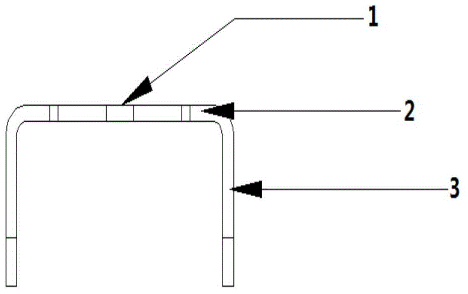
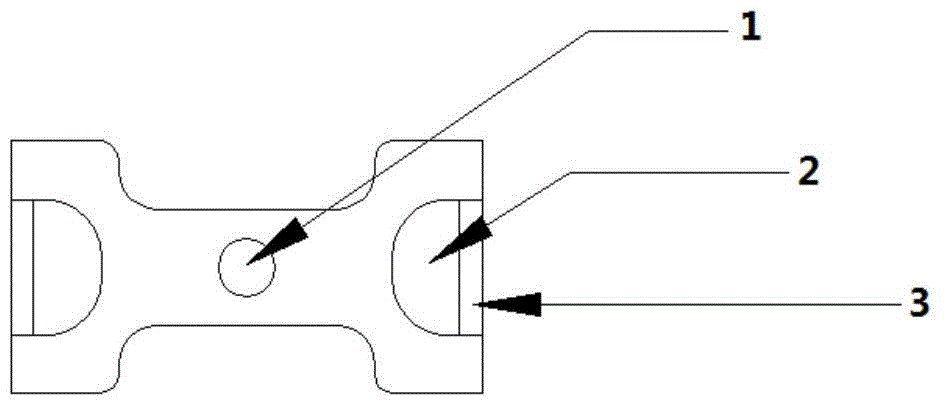
[0025] Such as figure 1 with figure 2 As shown, a capacitive coupling structure for metal cavity filter products, the structure is U-shaped or inverted U-shaped, including a lateral support medium and coupling plates 3 installed at both ends of the transverse support medium, and each coupling plate has a There are U-shaped holes 2 for metal debugging screws to pass through. The metal debugging screws on the cover plate can be adjusted in the U-shaped holes 2 of the coupling sheets on both sides to achieve the purpose of variable coupling capacitance.

[0026] Medium screw holes 1 for medium screws to pass through are provided on the lateral support medium. The medium screw hole 1 is provided with one center position for laterally supporting the medium. The lateral support medium is provided with symmetrically arranged U-shaped grooves.

[0027] The capacitive coupling structure of the metal filter product, the adjustable coupling screw of the U-shaped hole 2 avoids contact...

Embodiment 2

[0029] There are multiple medium screw holes 1 arranged horizontally or vertically. All the other are with embodiment 1.


PUM


Abstract

The invention relates to a capacitive coupling structure for a metal cavity filter product. The structure is of a U form or an inverted U form, and comprises a horizontal support medium and coupling sheets arranged at two ends of the horizontal support medium, wherein a U-shaped hole through which a metal debugging screw passes is formed in each coupling sheet. Compared with the prior art, the capacitive coupling structure has the advantage that the problem of the consistency of products with stringent inhibition requirements during production is solved.

Description

technical field [0001] The invention relates to a capacitive coupling structure, in particular to a capacitive coupling structure for metal cavity filter products. Background technique [0002] Microwave refers to signals in the frequency band between 300MHz (1MHz=1.0×10E6Hz) and 300GHz (1GHz=1.0×10E9Hz). Microwave communication originated from the radar technology developed in World War II. It has been widely used in long-distance communication networks all over the world. Due to its wide frequency bandwidth and large capacity, it can be used for the transmission of various telecommunication services, such as telephone, telegraph , data, fax and color TV, etc., its share in network erection is accelerating. Therefore, the research of microwave communication is of great significance to the development of national economy and the satisfaction of social needs. [0003] The most basic microwave communication system is to establish a microwave communication connection between ...

Claims


Application Information

Patent Timeline
Patent Type & Authority Applications(China)
IPC IPC(8): H01P1/207H01P7/06
Inventor 王邦林
Owner KAELUS COMM EQUIP SHANGHAI
Why Eureka
Try Eureka