Antenna structure processing method

A processing method and antenna structure technology, which are applied to antennas, devices that make antennas work in different frequency bands at the same time, and radiating element structure forms, etc. problem, to achieve the effect of adjusting, ensuring the integrity of the appearance, and realizing the frequency of the antenna

Inactive Publication Date: 2017-01-04
SAMSUNG GUANGZHOU MOBILE R&D CENT +1
View PDF5 Cites 1 Cited by
  • Summary
  • Abstract
  • Description
  • Claims
  • Application Information

AI Technical Summary

Problems solved by technology

[0004] from figure 1 It can be seen that the plastic partition in the existing three-segment antenna structure is obvious, which leads to a decrease in the overall aesthetics of the electronic terminal, and the existing three-segment antenna structure design leads to a fixed antenna shape, and it is impossible to realize the control of the antenna frequency. adjust

Method used


Image

  • Antenna structure processing method
  • Antenna structure processing method
  • Antenna structure processing method

Examples


Embodiment Construction

[0040] Hereinafter, embodiments of the present application will be described in detail with reference to the accompanying drawings.

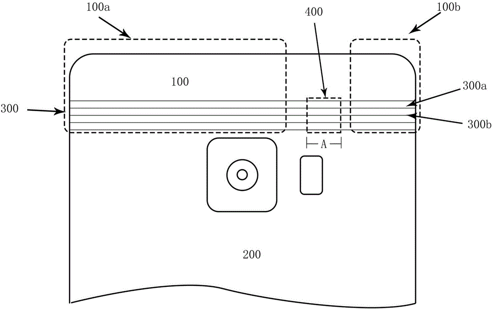
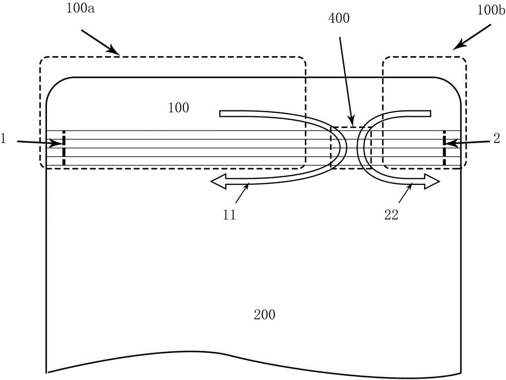
[0041] figure 2 A schematic diagram showing an antenna structure according to an exemplary embodiment of the present application.

[0042] Such as figure 2 As shown, the antenna structure according to the exemplary embodiment of the present application may include a first conductive body 100 , a second conductive body 200 , a non-signal shielding microstructure 300 and at least one conductive connection structure 400 . Refer below figure 2 Taking a conductive connection structure 400 as an example to introduce the composition and working principle of the antenna structure of the present application.

[0043] Specifically, one of the first conductive body 100 and the second conductive body 200 may constitute a radiation element of the antenna structure, and the other of the first conductive body 100 and the second conductive body 200 may co...


PUM


Abstract

The present invention provides an antenna structure processing method, comprising: providing a conductive shell, wherein the conductive shell comprises a first conductive body, a second conductive body, and a preset region comprising a first surface and a second surface which are oppositely arranged; forming at least one support structure on the first surface of the preset region, to enable the at least one support structure to be convexly arranged on the first surface; processing in the direction from the second surface to the first surface, and cutting through the preset region to form a preset number of micro seams; filling each micro seam with non-conductive material, to make the preset region become a non-signal shielding microstructure; and removing remaining support structures in the at least one support structure other than the designated support structure. By means of the antenna structure processing method in the exemplary embodiment of the present invention, since the seam width of each micro seam is relatively narrow, the proportion of the non-conductive material of the antenna structure is reduced, and the appearance integrity of the antenna structure is guaranteed; and since the designated support structure is reserved, the electrical length of an antenna can be changed, so that the antenna frequency is adjusted.

Description

technical field [0001] The present application relates to the technical field of electronic equipment, and more specifically, relates to an antenna structure processing method capable of improving antenna performance. Background technique [0002] At present, for the existing electronic terminals with metal bodies, there has always been a problem that the signal of the antenna is shielded. Therefore, most electronic terminals with metal bodies generally isolate some areas (clearance areas) for signals to pass through. [0003] In the prior art, the commonly used antenna design method is a three-segment antenna structure, such as figure 1 As shown, the existing three-section antenna structure divides the metal back cover of the electronic terminal into three parts, and a plastic partition is set between two adjacent parts, so that the signal can pass through the plastic partition to avoid being shielded. Next, the plastic partition completely separates two adjacent parts. ...

Claims


Application Information

Patent Timeline
Patent Type & Authority Applications(China)
IPC IPC(8): H01Q5/307H01Q5/328H01Q1/44H01Q1/36H01Q1/12
CPCH01Q5/307H01Q1/12H01Q1/36H01Q1/44H01Q5/328
Inventor 郝锐付堉皓
Owner SAMSUNG GUANGZHOU MOBILE R&D CENT
Why Eureka
Try Eureka