Chip power supply circuit, chip, ink cartridge

A technology for power supply circuits and chips, applied in battery circuit devices, circuit devices, current collectors, etc., can solve the problems of wasting power, long capacitor charging time, and troublesome battery replacement and maintenance.

Active Publication Date: 2019-03-08
HANGZHOU CHIPJET TECH
View PDF5 Cites 0 Cited by
  • Summary
  • Abstract
  • Description
  • Claims
  • Application Information

AI Technical Summary

Problems solved by technology

This will cause the capacitor charging time to be too long (the power-on time reaches the second level), and the chip will not respond to the printer command in time during the printer recognition process and cause an error
However, if the battery alone is used to power the chip, the charge on the battery will be drained very quickly
Not only is power wasted, but battery replacement and maintenance are troublesome

Method used


Image

  • Chip power supply circuit, chip, ink cartridge
  • Chip power supply circuit, chip, ink cartridge
  • Chip power supply circuit, chip, ink cartridge

Examples


Embodiment 1

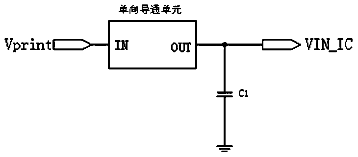
[0029] An ink box, the ink box chip includes a chip circuit and a chip power supply circuit. The main input terminal Vprint of the chip power supply circuit is used to electrically connect with the power output terminal of the printer, and the main output terminal VIN_IC of the chip power supply circuit is connected to the power input terminal of the chip circuit.

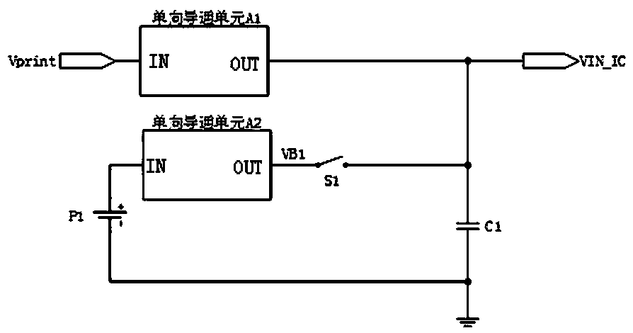
[0030] Such as image 3 , the total input terminal Vprint of the chip power supply circuit is connected to the total output terminal VIN_IC through the unidirectional conduction unit A1, the input terminal of the unidirectional conduction unit A1 is connected to the total input terminal Vprint, and the output terminal of the unidirectional conduction unit A1 is connected to the total output terminal VIN_IC. The negative pole of the battery P1 is grounded, and a one-way conduction unit A2 and a controlled switch S1 are provided between the positive pole of the battery P1 and the total output terminal VIN_IC. The in...

Embodiment 2

[0038] The chip circuit pulls Battery_EN high at the beginning of each command (not just the characteristic command) of the printer, and the path from the battery to the power input terminal of the chip circuit is turned on, and keeps Battery_EN high for t3 time (greater than 100ms). After t3, battery_EN is pulled low, and the path from the battery to the power input terminal of the chip circuit is disconnected.


PUM


Abstract

The invention relates to a chip power supply circuit, in particular to a chip power supply circuit for switching the power supply from printer power supplies to a battery, a chip using the chip power supply circuit, and an ink box. The chip power supply circuit comprises a total input end, a total output end, a capacitor, a second power supply and a switch unit, wherein the total input end is used for being connected with a first power supply, the total output end is used for being connected with the chip, the total input end is connected with the total output end, one end of the capacitor is connected with the total output end, and the other end of the capacitor is grounded; the output end of the second power supply is connected to the total output end through the switch unit; the switch unit is on when the first power supply fails for a long time, and the second power supply is connected to supply power for the chip; the switch unit is off when the first power supply fails in a short time, and the electric connection between the second power supply and the chip is disconnected. The chip power supply circuit, the chip and the ink box have the advantages that the battery and a printer are used to supply power for the chip, battery electric quantity is saved greatly, and the response speed of the chip when the chip is mounted onto the printer for certification.

Description

technical field [0001] The invention relates to a chip power supply circuit, in particular to a chip power supply circuit for switching printer power supply and battery power supply, and a chip and an ink cartridge using the chip power supply circuit. Background technique [0002] When the printer is working, the power supply to the ink cartridge chip is not continuous. When the printer is working, it will experience different periods of power failure (such as figure 1 ). At this time, the chip cannot get power from the printer to maintain its normal operation. [0003] Existing technologies usually use such as figure 2 In the technical solution shown, an external capacitor C1 is connected between the chip power input terminal VIN_IC and the printer power output terminal Vprint. When the printer is powered, the external capacitor C1 charges and stores energy; when the printer is powered off, the external capacitor C1 discharges to keep the chip working, and a one-way co...

Claims


Application Information

Patent Timeline
Patent Type & Authority Patents(China)
IPC IPC(8): H02J9/06H02J7/00B41J2/175
CPCB41J2/1753H02J7/00H02J7/345H02J9/061
Inventor 胡容铭彭新平黄海霞虞少平余海建
Owner HANGZHOU CHIPJET TECH
Why Eureka
Try Eureka