Bone lengthening scaffold

A technology of bone extension and assembly, applied in medical science, surgery, etc., can solve the problems of small rotation angle, short inconvenient distance, difficult use, etc., and achieve the effect of precise angle

Inactive Publication Date: 2017-01-11
SUZHOU YINUOSI MEDICAL TECH
View PDF6 Cites 10 Cited by
  • Summary
  • Abstract
  • Description
  • Claims
  • Application Information

AI Technical Summary

Problems solved by technology

[0004] However, the existing medical bone extension brackets have a fixed length and size and cannot be adjusted reasonably according to different situations. The adjustment is inc

Method used


Image

  • Bone lengthening scaffold
  • Bone lengthening scaffold
  • Bone lengthening scaffold

Examples


Embodiment Construction

[0042] The technical solution of a bone extension stent involved in the present invention is further described in non-limiting detail below with reference to the preferred embodiments and the accompanying drawings.

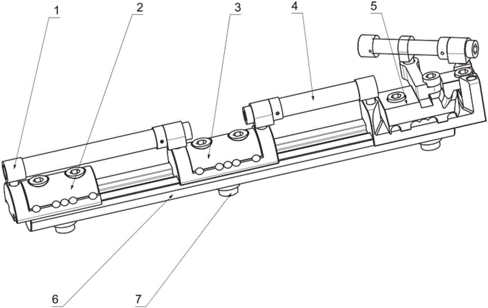
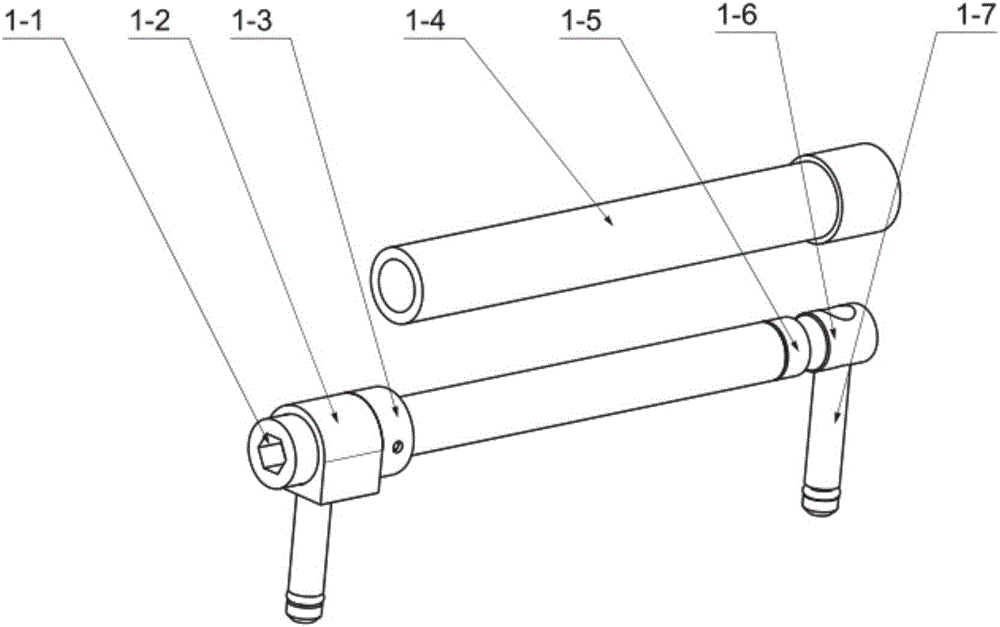
[0043] see figure 1 As shown, an embodiment of the present invention provides a bone extension bracket, which includes a first link assembly 1, a front end adapter slider assembly 2, a middle end adapter slider assembly 3, a second link assembly 4, The tail end rotates the slider assembly 5 and the guide rail 6 .

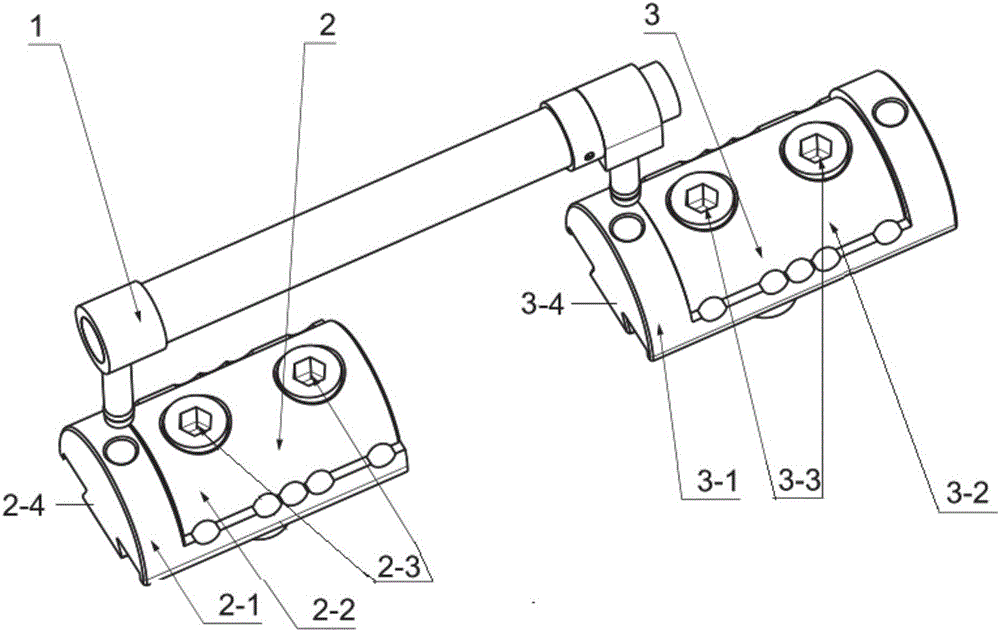
[0044] The guide rail 6 is the main support, and the front end adapter slider assembly 2 , the middle end adapter slider assembly 3 and the rear end rotary slider assembly 5 are connected together by screws 7 . Through the trapezoidal groove 6-1 on the guide rail 6 (such as Image 6 shown) and the protruding trapezoidal features 2-4, 3-4 on each of the slider assemblies (as shown in figure 2 The three types of slider assemblies are adjusted in posit...


PUM


Abstract

The invention discloses a bone lengthening scaffold. The bone lengthening scaffold comprises a first connecting rod assembly, a front end transfer sliding block assembly, a tail end rotating sliding block assembly and sliding rails, wherein the guide rails serve as a main scaffold; the front end transfer sliding block assembly and the tail end rotating sliding block assembly are connected onto the guide rails in a sliding fit manner; the first connecting rod assembly is connected with the front end transfer sliding block assembly and the tail end rotating sliding block assembly. The positions of the front end transfer sliding block assembly and the tail end rotating sliding block assembly on the sliding rails can be adjusted by adjusting the first connecting rod assembly.

Description

technical field [0001] The invention relates to a medical bone extension bracket. Background technique [0002] With the development of society and the advancement of science and technology, people's living standards have been continuously improved. With the improvement of people's living standards, people's attention to health is also gradually increasing, which also leads to the continuous improvement of medical conditions and promotes the development of medical devices. [0003] For example, taking bone lengthening surgery as an example, a bone lengthening bracket is usually used to fix the broken bone. [0004] However, the existing medical bone extension brackets have a fixed length and size, and cannot be reasonably adjusted according to different situations. The adjustment is inconvenient, the distance is short, the amount of joint movement or the rotation angle is small, the adjustment is imprecise, the overall weight is large, and the use is difficult. [0005] Th...

Claims


Application Information

Patent Timeline
IPC IPC(8): A61B17/60
CPCA61B17/60A61B2017/564
Inventor 李根王晓燕王熙迥沈士明
Owner SUZHOU YINUOSI MEDICAL TECH
Why Eureka
Try Eureka