Push-pull feeding device

A push-pull and pull-rod technology, applied in the field of push-pull feeding devices, can solve the problems of laborious, difficult positioning, etc.

Active Publication Date: 2017-01-11
ANHUI JIANGHUAI AUTOMOBILE GRP CORP LTD
View PDF6 Cites 4 Cited by
  • Summary
  • Abstract
  • Description
  • Claims
  • Application Information

AI Technical Summary

Problems solved by technology

[0004] The invention provides a push-pull type feeding device, which solves the problems of laborious feeding process during the processing of the existing engine cylinder block, and the difficult positioning of the cylinder block when i

Method used


Image

  • Push-pull feeding device
  • Push-pull feeding device
  • Push-pull feeding device

Examples


Embodiment Construction

[0068] In order to enable those skilled in the art to better understand the solutions of the embodiments of the present invention, the embodiments of the present invention will be further described in detail below in conjunction with the drawings and implementations.

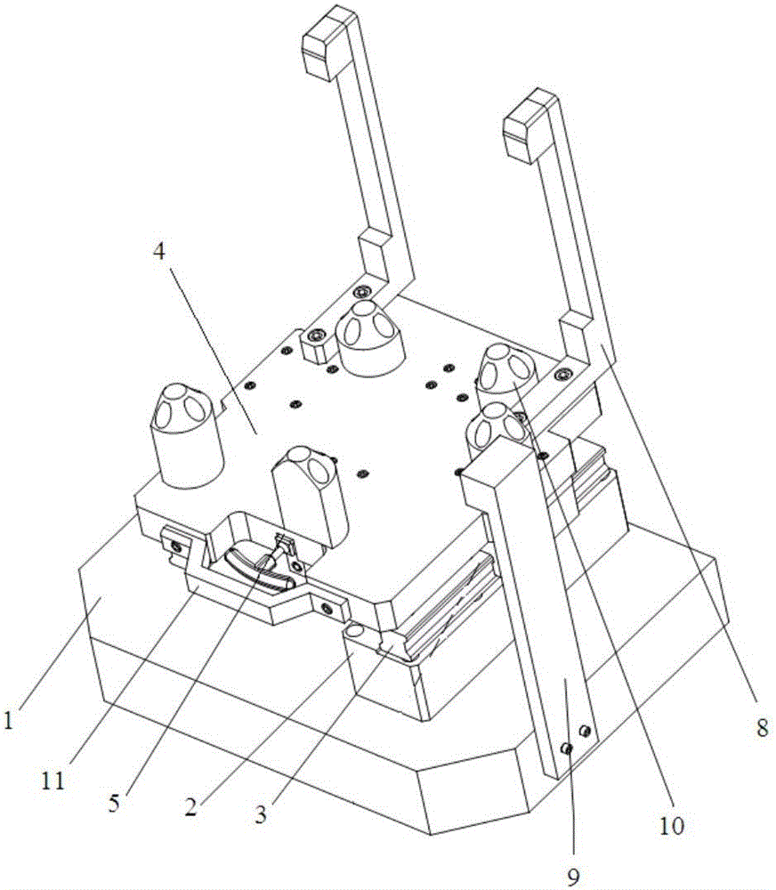
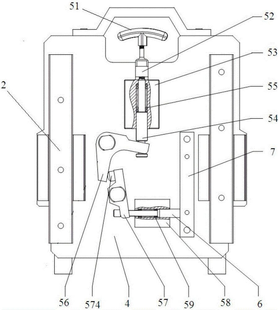
[0069] Aiming at the current engine cylinder operation, the positioning of the cylinder requires a lot of labor. The invention provides a push-pull type feeding device, which drives the limit pin through the push-pull transmission mechanism to complete the plug-in and out-of-pin action, and solves the problem of existing engine cylinder processing. At the same time, the feeding process is laborious, and the problem of difficult positioning of the cylinder block when the pin is inserted and the laborious problem of the pin is reduced, which reduces the difficulty of feeding the engine block when the engine block is in the side lying position, and improves the production efficiency and safety of the automobile.

[00...


PUM


Abstract

The invention relates to a push-pull feeding device which comprises a fixture bottom plate, two supporting blocks, sliding rails, a sliding plate, a push-pull drive mechanism, limit pins and limit seats. The two parallel supporting blocks are fixed at the set positions on the fixture bottom plate, the sliding rails and the limit seats are arranged on the upper surfaces of the supporting blocks, the sliding rails are positioned on the outer sides of the limit seats, the sliding plate translates and slides through the sliding rails, guide blocks are arranged on the periphery of the sliding plate, and the push-pull drive mechanism and the limit pins are arranged on the bottom surface of the sliding plate. In the feeding process of a cylinder, the sliding plate translates and slides to the designated position, and the push-pull drive mechanism drives the limit pins to be inserted into or pulled out of the limit seats, so that the cylinder and a fixture are accurately positioned and clamped by translating and sliding of the sliding plate. The push-pull feeding device can solve the problems that when an existing engine cylinder is machined, the feeding process is strenuous, and the cylinder is not easily positioned when the pins are inserted, pin pulling is strenuous, and automobile production efficiency and safety are improved.

Description

technical field [0001] The invention relates to the field of automobile production auxiliary technologies, in particular to a push-pull type feeding device. Background technique [0002] The material of the engine block is generally gray cast iron, which is heavy and has a complex shape and structure. When manual loading is used to enter the processing fixture, if the processing reference is two pins on one side of the bottom surface, and the processing posture is side lying, that is, the top surface of the workpiece faces It is extremely difficult for the operator to operate with the intake side or exhaust side facing down (the clamps in the side lying posture of the cylinder body are generally L-shaped back-plate structures, that is, the positioning and clamping points are arranged on the back plate, facing the direction of the operator ). It will not only affect the feeding time of the cylinder, but also easily cause the collision between the positioning pin and the posi...

Claims


Application Information

Patent Timeline
IPC IPC(8): B23Q7/00
CPCB23Q7/00
Inventor 杨健黄浩段昌凯谢飞汤善荣
Owner ANHUI JIANGHUAI AUTOMOBILE GRP CORP LTD
Why Eureka
Try Eureka