Device for automatically measuring thickness of nuclear fuel plate

A technology of plate thickness and nuclear fuel, which is applied in the direction of measuring devices, optical devices, instruments, etc., can solve the problems of increasing feeding time, low detection accuracy, and vibration, so as to improve detection accuracy, improve detection efficiency, and reduce the burden on The effect of material difficulty

Pending Publication Date: 2021-05-25
四川同人精工科技有限公司 +1
View PDF0 Cites 1 Cited by
  • Summary
  • Abstract
  • Description
  • Claims
  • Application Information

AI Technical Summary

Problems solved by technology

However, although this measurement method can measure the thickness of the nuclear fuel plate, it still has the following defects: 1. Before the measurement, the laser displacement sensor needs to be moved, and vibration will inevitably occur during the movement, which will lead to inaccurate data measured by the laser displacement sensor, thereby reducing The accuracy of thickness measurement
2. The nuclear fuel plate is transferred to the detection station by the mechanical arm. Before the mechanical arm grabs the nuclear fuel plate, the worker needs to stack the nuclear fuel plate in the designated area of ​​the loading rack to ensure that the mechanical arm can accurately grasp it. Nuclear fuel plates in a designated area, but when manually stacking nuclear fuel plates on the loading rack, it is difficult to ensure that the nuclear fuel plates are accurately positioned on the loading rack, which increases the difficulty of loading nuclear fuel plates, and requires workers to place them one by one The nuclear fuel plates are stacked on the loading rack, which increases the loading time and reduces the detection efficiency of the nuclear fuel plate thickness
3. The thickness detection standard is single-point thickness, which does not meet the detection standard and the detection accuracy is low

Method used


Image

  • Device for automatically measuring thickness of nuclear fuel plate
  • Device for automatically measuring thickness of nuclear fuel plate
  • Device for automatically measuring thickness of nuclear fuel plate

Examples


Embodiment Construction

[0029] The present invention will be further described below in conjunction with accompanying drawing, protection scope of the present invention is not limited to the following:

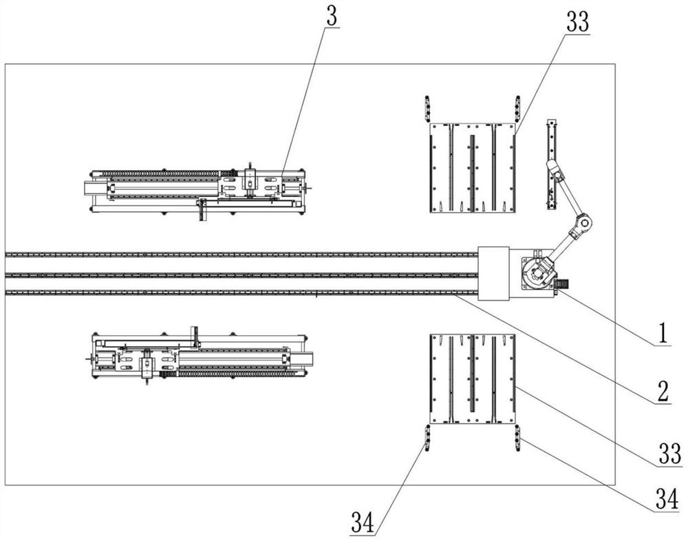
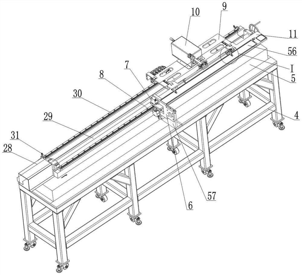
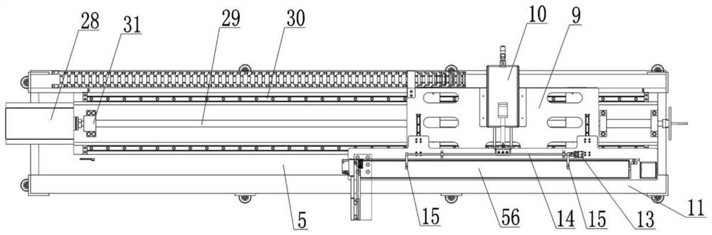
[0030] Such as Figure 1-13 As shown, a device for automatically measuring the thickness of a nuclear fuel plate includes a robot grabbing system 1 and a robot track 2, the front and rear sides of the robot track 2 are provided with a plate thickness detection device 3, and the robot grabbing system 1 is arranged on the robot On the track 2 and can move along the robot track 2, a grabbing device is arranged on the output shaft of the robot grabbing system 1, and the plate thickness detection device 3 includes a chassis 4 and a platform 5, the platform 5 is a marble platform, and the platform 5 Be located on the top surface of underframe 4 and be fixed with support seat 57, be provided with support 6 with opening on support seat 57, be provided with upper laser displacement sensor 7 and lower laser di...


PUM


Abstract

The invention discloses a device for automatically measuring the thickness of a nuclear fuel plate. The device comprises a robot grabbing system (1) and a robot track (2); the front and rear sides of the robot track (2) are respectively provided with plate thickness detection devices (3); the robot grabbing system (1) is arranged on the robot track (2) and can move along the robot track (2); a grabbing device is arranged on an output shaft of the robot grabbing system (1); each plate thickness detection device (3) comprises a bottom frame (4) and a platform (5), wherein the platform (5) is fixedly arranged on the top surface of the bottom frame (4) and fixedly provided with a supporting seat (57); a support (6) with an opening is fixedly arranged on each supporting seat (57); and an upper laser displacement sensor (7) and a lower laser displacement sensor (8) are arranged on each support (6). The device is compact in structure, can improve nuclear fuel plate detection efficiency, improve nuclear fuel plate thickness detection accuracy, and reduce nuclear fuel plate feeding difficulty.

Description

technical field [0001] The invention relates to the technical field of thickness detection of nuclear fuel plates, in particular to a device for automatically measuring the thickness of nuclear fuel plates. Background technique [0002] The nuclear fuel plate is a strip-shaped plate with a certain thickness. After its production and molding, its thickness needs to be tested. The purpose is to eliminate the nuclear fuel plate whose thickness does not meet the requirements. The existing detection method is to first hang the nuclear fuel plate to be tested horizontally, and then use two laser displacement sensors to irradiate the upper surface and the lower surface of the nuclear fuel plate respectively to measure the thickness of the nuclear fuel plate. However, although this measurement method can measure the thickness of the nuclear fuel plate, it still has the following defects: 1. Before the measurement, the laser displacement sensor needs to be moved, and vibration will i...

Claims


Application Information

Patent Timeline
Patent Type & Authority Applications(China)
IPC IPC(8): G01B11/06
CPCG01B11/06
Inventor 刘明李晨浩张雷程春林金凡尧
Owner 四川同人精工科技有限公司
Why Eureka
Try Eureka