
3D printer

A 3D printer and printing table technology, applied in the field of 3D printing, can solve the problem of difficult to control the three-dimensional position, and achieve the effect of improving the printing quality

Inactive Publication Date: 2017-01-11
CHENGDU JINCAI TECH
View PDF5 Cites 0 Cited by
  • Summary
  • Abstract
  • Description
  • Claims
  • Application Information

AI Technical Summary

Problems solved by technology

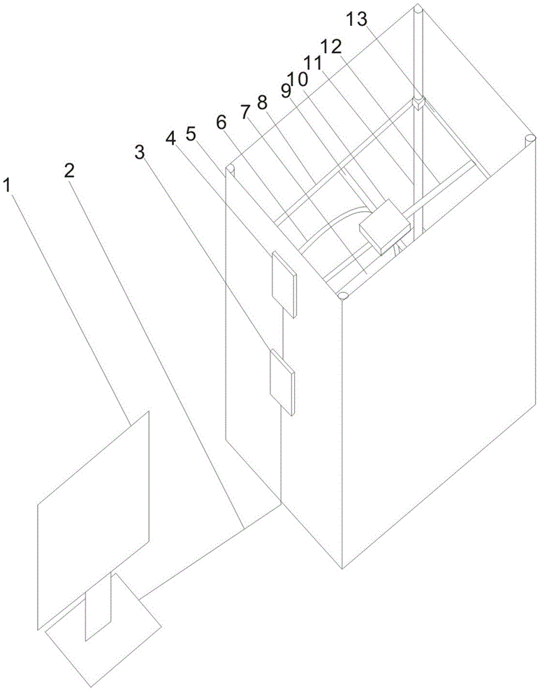
[0003] The purpose of the present invention is: in order to solve the above problems, the present invention proposes a 3D printer, which solves the problems in the prior art that the three-dimensional position is difficult to control during 3D printing.

Method used


Image

  • 3D printer

Examples


Embodiment Construction

[0010] In order to make the objectives, technical solutions and advantages of the present invention clearer, the present invention will be further described in detail below with reference to the accompanying drawings and embodiments. It should be understood that the specific embodiments described herein are only used to explain the present invention, but not to limit the present invention.

[0011] like figure 1 As shown, it is a schematic structural diagram of the 3D printer of the present invention. The 3D printer of the present invention includes a processing device 1, a control device 3, a power device 4, a printing table 5, a printing head 6, and a sliding device. The printing table 5 is composed of a side wall located on the side and an object platform 7 located at the bottom. , the sliding device is arranged inside the printing table 5, and the sliding device is composed of a guide column 11 vertically installed on the four corners of the side wall of the printing plat...


PUM


Abstract

The invention discloses a 3D printer. The 3D printer comprises a processing apparatus, a control apparatus, a power apparatus, a printing bench, a print head, and a weight calculation device. A slide apparatus is arranged in the printing bench, is composed of the guide pillars vertically arranged at four angles of the side wall of the printing bench, a guide rail horizontally arranged on the guide pillar and a guide rod arranged on the guide rail; a slide unit is arranged on the guide rod, the control apparatus and the power apparatus are positioned at the side wall of the printing bench, the processing apparatus and the control apparatus are connected by employing a lead, the control apparatus and the power apparatus are connected by employing the lead. According to the invention, by controlling the slide apparatus by the processing apparatus, the control apparatus and the power apparatus, three-dimensional fixed-point printing is realized by the print head, and the printing quality is increased.

Description

technical field [0001] The invention belongs to the technical field of 3D printing, and particularly relates to a 3D printer. Background technique [0002] Existing engineering models, such as architectural models, are generally made by lap jointing and pasting with iron wires or plastics by hand, which requires a lot of manpower and material resources. In particular, some building models with complex structures and special nodes consume more man-hours, and the assembled building models are unstable and prone to collapse. In addition, for relatively fine architectural models, hand-made is difficult to achieve. Existing engineering models, such as architectural models, are generally made by lap jointing and pasting with iron wires or plastics by hand, which requires a lot of manpower and material resources. In particular, some building models with complex structures and special nodes consume more man-hours, and the assembled building models are unstable and prone to collaps...

Claims


Application Information

Patent Timeline
Patent Type & Authority Applications(China)
IPC IPC(8): B29C67/00B33Y30/00
Inventor 蓝奕冰
Owner CHENGDU JINCAI TECH
Learn More