
Address coding method and address coding system for cascaded device and lighting system

An address coding and cascading technology, applied in the field of coding, can solve the problems that multiple lighting devices cannot be applied to the hot-swap environment, poor compatibility, and unable to code and control the light source drive circuit, and achieve safe light source drive performance, simplified control steps, The effect of improving address coding control efficiency and control precision

Active Publication Date: 2019-12-13
SHENZHEN SUNMOON MICROELECTRONICS
View PDF7 Cites 1 Cited by
  • Summary
  • Abstract
  • Description
  • Claims
  • Application Information

AI Technical Summary

Problems solved by technology

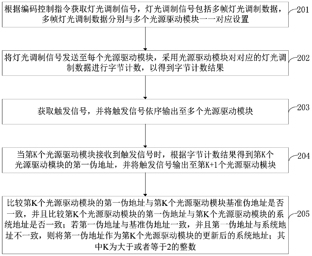
[0004] In view of this, the embodiment of the present application provides an address coding method, an address coding system, and a lighting system for a cascaded device, aiming at solving the problem that the traditional technical solution requires an additional coded data stream to be compatible with the light source driving circuit when performing address coding. The performance is poor, and it is impossible to control multiple light source driving circuits through flexible coding, resulting in the problem that multiple lighting devices cannot be applied to the hot-swappable environment

Method used


Image

  • Address coding method and address coding system for cascaded device and lighting system
  • Address coding method and address coding system for cascaded device and lighting system
  • Address coding method and address coding system for cascaded device and lighting system

Examples


Embodiment Construction

[0058] In order to make the purpose, technical solution and advantages of the present application clearer, the present application will be further described in detail below in conjunction with the accompanying drawings and embodiments. It should be understood that the specific embodiments described here are only used to explain the present application, and are not intended to limit the present application.

[0059] In order to more clearly illustrate the specific operation principle of the address encoding method in this embodiment, figure 1 shows the schematic structure of the cascaded equipment provided by this embodiment, please refer to figure 1 , wherein the cascade device includes: a plurality of cascaded light source driving modules, wherein each light source driving module has a light source driving function, through which the light source driving module can drive at least one LED lamp in real time to achieve a luminous effect, and adjust the corresponding LED lamp Lu...


PUM


Abstract

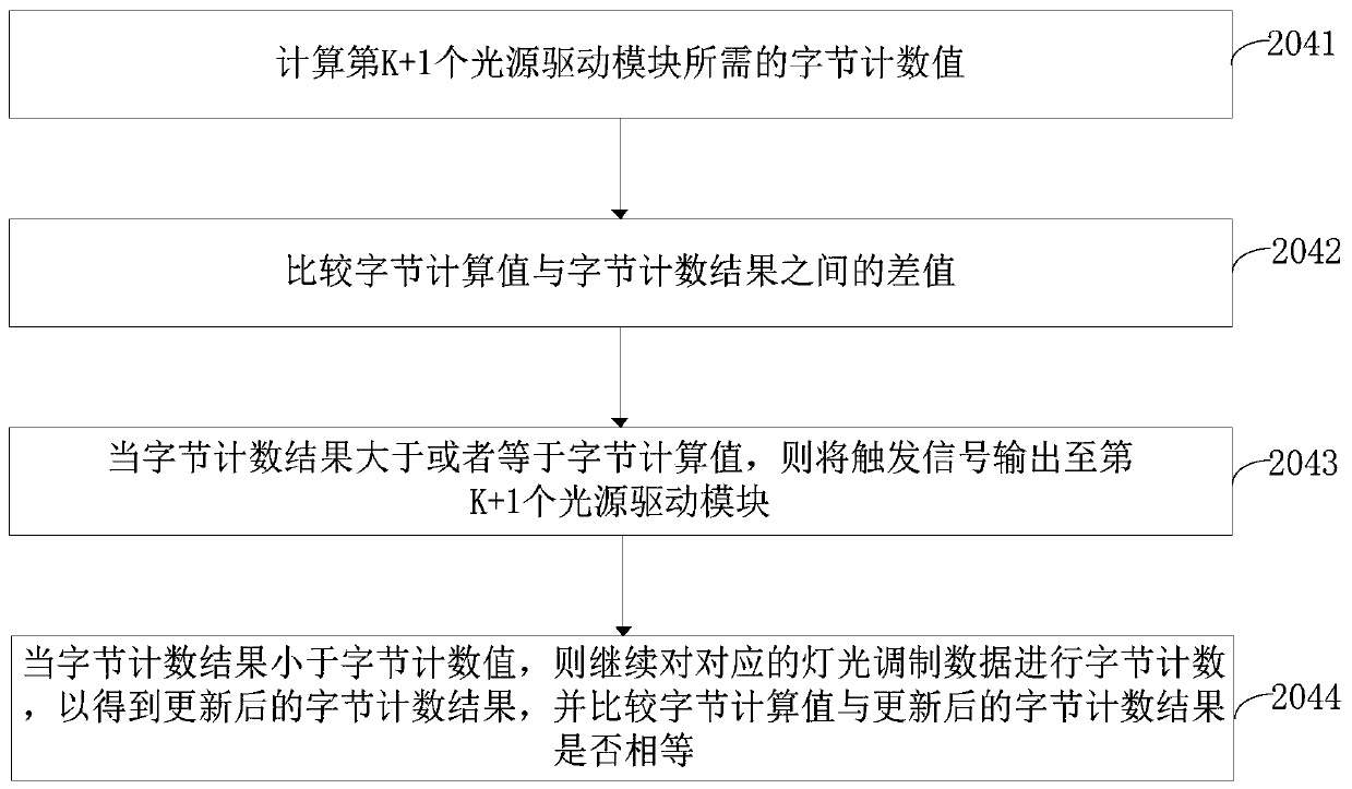
The invention provides an address coding method and an address coding system for a cascaded device and a lighting system. The address coding method comprises the steps that a light modulation signal is output to each light source driving module; when a light source driving module receives a trigger signal, the light source driving module is driven by the trigger signal to start an address coding function, which guarantees the address coding efficiency and control response accuracy of multiple light source driving modules; when each light source driving module starts address coding, the light source driving module counts the corresponding light modulation data; the first pseudo address of the light source driving module is acquired according to the counting result of the light modulation data; the first pseudo address and the reference pseudo address are verified to determine whether the first pseudo address meets the address writing requirement of the light source driving module to complete the real-time update of the system address of the light source driving module, and the accuracy and efficiency of address writing are high; and the address writing process of the cascaded devicehas high compatibility and flexibility.

Description

technical field [0001] The present application belongs to the field of encoding technology, and in particular relates to an address encoding method, an address encoding system and a lighting system for cascade equipment. Background technique [0002] With the rapid development of modern science and technology, lighting equipment has penetrated into various technical fields of people's production and life. Among them, lighting equipment can not only meet people's daily lighting needs, but also bring great convenience to people's production and life. The light source can realize the effect of landscape and lighting, and bring people a good visual experience; and with the continuous improvement of people's lighting performance, technicians need to use integrated and large-scale lighting equipment to achieve better luminous performance. Through The drive circuit can synchronously control multiple lighting devices to emit more coordinated and consistent light sources; and when mu...

Claims


Application Information

Patent Timeline
Patent Type & Authority Applications(China)
IPC IPC(8): H05B33/08H05B44/00
CPCY02B20/40
Inventor 李照华郭伟峰陈克勇
Owner SHENZHEN SUNMOON MICROELECTRONICS
Learn More