Fuel injector and control valve thereof

A technology for controlling valves and injectors, which is applied to fuel injection devices, fuel injection devices with anti-corrosion measures, machines/engines, etc., to achieve reliable functions

Active Publication Date: 2017-01-11
ROBERT BOSCH GMBH
View PDF5 Cites 0 Cited by
  • Summary
  • Abstract
  • Description
  • Claims
  • Application Information

AI Technical Summary

Problems solved by technology

[0004] The purpose of this application is to improve the fuel injector to alleviate o

Method used


Image

  • Fuel injector and control valve thereof
  • Fuel injector and control valve thereof
  • Fuel injector and control valve thereof

Examples


Embodiment Construction

[0024] Some possible implementations of the present application are described below with reference to the accompanying drawings.

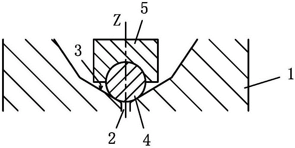
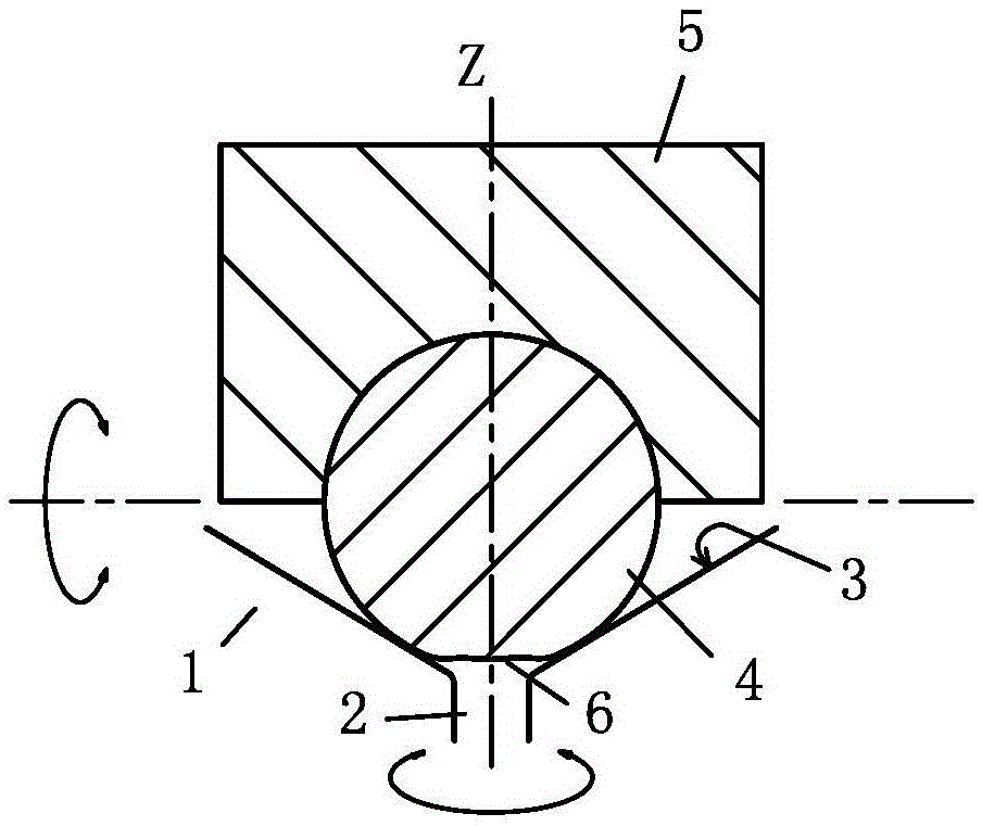
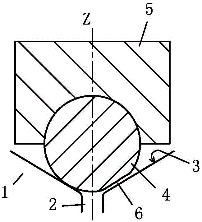
[0025] Figure 4 The middle part shows a fuel injector for injecting fuel into an engine according to a possible embodiment of the present application, especially an injector in a diesel common rail injection system. The fuel injector comprises a control valve and an injection valve assembled together, for example, they may be assembled in a common injector housing 8 (not shown in detail). The improvements of this application relate to control valves, therefore Figure 4 Only the relevant part of the control valve is shown in . The injection valve is combined on the front side of the control valve ( figure 1 the lower side in the center), toward the engine. The control valve is switchable between an open state and a closed state. By controlling the opening and closing state of the valve, the fuel injection action of the injection valve is cont...


PUM


Abstract

The invention discloses a fuel injector and a control valve thereof. The control valve comprises a valve seat, a valve element and a retaining block, wherein a valve seat surface and a valve hole penetrating through the center of the valve seat surface longitudinally are defined in the valve seat; the valve hole and the valve seat surface define a longitudinal central axis; the valve hole communicates with an injection valve of the fuel injector; the valve element is constructed to be suitable for moving between a valve closing position and a valve opening position along the longitudinal central axis; in the valve closing position, the valve element makes contact with the valve seat in a matched mode to close the valve hole, and in the valve opening position, the valve element leaves the valve seat to opening the valve hole; and the retaining block is provided with a containing groove used for retaining the valve element. The valve element is a rotary body with the longitudinal central axis as the rotation center. The longitudinal section of the valve element including the longitudinal central axis is noncircular so that the valve element can rotate around the longitudinal central axis, but cannot rotate around any transverse central axis perpendicular to the longitudinal central axis.

Description

technical field [0001] The present application relates to a control valve for use in a fuel injector, and a fuel injector, in particular a common rail injector, comprising such a control valve. Background technique [0002] A fuel injector usually includes a control valve and an injection valve, and the fuel injection action of the injection valve is controlled by the opening and closing state of the control valve. figure 1 A partial structure of the control valve is schematically shown in , the control valve includes a valve seat 1, which is formed with a valve hole 2 and a valve seat surface 3; a spherical valve core 4, which cooperates with the valve seat surface 3 to realize the valve Opening and closing of the hole 2; holding block 5, which houses a part of the spool 4 and is used to push the spool 4 to the position of closing the hole 2. The valve hole 2, the valve core 4 and the holding block 5 are arranged along the central axis Z extending longitudinally of the con...

Claims


Application Information

Patent Timeline
IPC IPC(8): F02M47/00F02M61/18
CPCF02M47/027F02M63/0031F02M63/0036F02M2200/05
Inventor 陈彦霖
Owner ROBERT BOSCH GMBH
Why Eureka
Try Eureka