A display support frame with a single shaft rod type column and a quick release

A display and support frame technology, which is applied in the direction of machines/stands, support machines, mechanical equipment, etc., can solve the problems of reducing packaging and transportation costs, complex column structures, and bloated, so as to reduce packaging and transportation costs, and reduce packaging and transportation costs. The effect of simple transportation volume and processing

Active Publication Date: 2018-08-21
TAIZHOU STRONKIN ELECTRONICS
View PDF8 Cites 0 Cited by
  • Summary
  • Abstract
  • Description
  • Claims
  • Application Information

AI Technical Summary

Problems solved by technology

However, in the prior art, the column may have a lifting function, which makes the internal and external structure of the column very complicated, resulting in a large cross-sectional size of the column, a thick and bloated shape; or although the lifting function is not required, the section of the column is basically a thick hollow circle. The cross-section or thick hollow polygonal cross-section or hypertrophic box-shaped cross-section, or narrow and flat but very narrow, long and flat, without a mechanism for quick release of the base from the column, cannot satisfy those who prefer a slender column and can be quickly disassembled at the same time People's requirements for the base are not conducive to reducing packaging, transportation volume, convenient packaging, reducing packaging and transportation costs, and are not conducive to environmental protection

Method used


Image

  • A display support frame with a single shaft rod type column and a quick release
  • A display support frame with a single shaft rod type column and a quick release

Examples


Embodiment Construction

[0019] In order to make the technical means, creative features, goals and effects achieved by the present invention easy to understand, the present invention will be further described below in conjunction with specific embodiments.

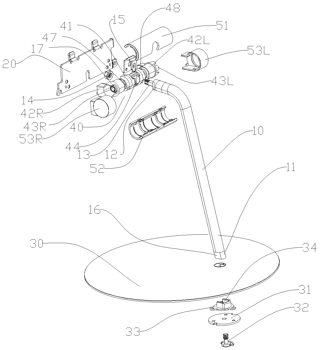
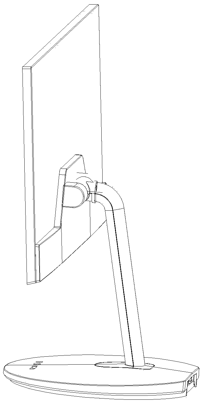
[0020] see figure 1 , figure 2 , the point is figure 1 (Please note that the references to the up, down, left and right directions in the present invention are viewed from the direction facing the display, the same below, and will not be described in detail). A display support frame with a single shaft-type column and quick release, including a base 30 (the body part is a plate-shaped stamped steel plate or a light alloy die-casting part, in this example a plate-shaped aluminum alloy die-casting part), installed on the base The column 10 on the 30 (can be formed by steel bar stock, also can adopt light alloy die-casting), the upper end of the column 10 is fixedly connected (multiple known fixing techniques in this industry can be used) and a hi...


PUM


Abstract

The invention relates to a display support frame provided with a single shaft lever type upright column and having a fast dismounted function. The display support frame comprises a base and the upright column mounted on the base, wherein the upper end of the upright column is fixedly connected with a screen connecting hinge assembly. The display support frame is characterized in that the upright column adopts a single shaft lever, the upper section of the upright column bends and extends forwards, a first locating plane is formed on the bottom surface of the lower end of the upright column, a second locating plane correspondingly adaptive to the first locating plane is formed on the base, and a threaded hole is formed in the lower end of the upright column; the display support frame further comprises a manual screw which is screwed manually into the threaded hole from the lower surface of the base and tightly presses and fixedly connects the second locating plane and the first locating plane; meanwhile, the section outline of a shaft section at the lower end of the upright column is non-circular, the base is provided with a corresponding rotation stopping clamping hole adaptive to the non-circular section of the shaft section at the lower end, and the rotation stopping clamping hole is used for mounting, wrapping, clamping and stopping rotation of the shaft section at the lower end. The upright column of the support frame is slender, concise and unique in appearance modeling and has unique style, and the base has a fast dismounted function.

Description

technical field [0001] The invention relates to a display support frame with a single shaft-type column and a quick release, which belongs to the field of support frames for displays, and in particular relates to the column structure, the screen joint hinge assembly and the base quick release mechanism (the present invention The monitors referred to include monitors that display movable images, including liquid crystal or LED monitors or display screens, including all-in-one machines and POS machines, hereinafter referred to as monitors or screens). Background technique [0002] With the vigorous development of digital audio and video, liquid crystal or LED displays are widely used, but most of the displays need to be installed on a support frame for ease of use. With the development of science and technology and society as well as the development of the display itself, people have higher and higher requirements for the supporting frame of the display, especially its appeara...

Claims


Application Information

Patent Timeline
Patent Type & Authority Patents(China)
IPC IPC(8): F16M11/24F16M11/10F16M11/16
Inventor 夏勇陈春
Owner TAIZHOU STRONKIN ELECTRONICS
Why Eureka
Try Eureka