Gas stove and assembly thereof

A technology of gas stoves and components, which is applied in the field of gas stoves, and can solve the problems that it is difficult to clean, and the screw is easy to become a hygienic dead corner.

Active Publication Date: 2017-01-11
BSH ELECTRICAL APPLIANCES JIANGSU +1
View PDF5 Cites 0 Cited by
  • Summary
  • Abstract
  • Description
  • Claims
  • Application Information

AI Technical Summary

Problems solved by technology

Since the burner base 2' and the liquid pan 11' are fixed together by screws, the screw is easy to become a hygienic corner and is not easy to clean

Method used


Image

  • Gas stove and assembly thereof
  • Gas stove and assembly thereof
  • Gas stove and assembly thereof

Examples


Embodiment 1

[0047] The present invention proposes an embodiment of a gas stove, including a gas stove assembly, an ignition needle 6 and a thermocouple 7 .

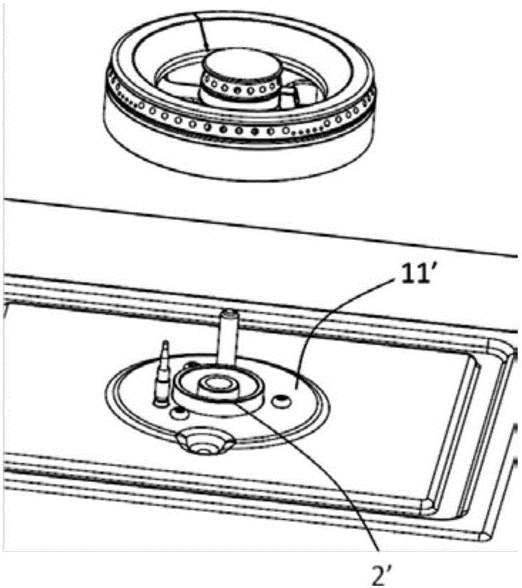
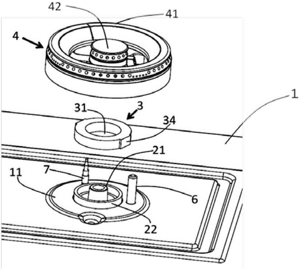
[0048] A gas stove assembly, including a panel 1, a burner base 2, a fixing piece 3, a burner 4 and a bottom case, such as Figures 3 to 5 shown. The panel 1 includes a liquid pan 11 made of stainless steel, and the liquid pan 11 is provided with a through hole. The bottom of the burner base 2 is fixed to the bottom shell. Both the ignition needle 6 and the thermocouple 7 are fixed on the burner base 2 , and the liquid pan 11 is provided with holes for respectively passing the ignition needle 6 and the thermocouple 7 .

[0049] The fixing part 3 has a ring-shaped structure and adopts an integrally formed structure. The fixing part 3 includes a hollow part 31, a ring-shaped groove 32 and two symmetrically arranged clamping parts 34, such as Figure 6 and 7 shown. The clamping part 34 adopts a raised structure, such as Figure 6 ...

Embodiment 2

[0057] The present invention also proposes another gas stove embodiment 2, which is further improved on the basis of the gas stove embodiment 1 above. The main differences between the second embodiment of the gas stove and the first embodiment of the gas stove are as follows.

[0058] The fixing part 3 of the gas cooker assembly of the gas cooker embodiment 2 is a nut structure, such as Figure 8 and 9 shown. The protrusion 24 of the outer tube 22 is provided with an external thread. The fixing member 3 is provided with an internal thread 33 matched with the external thread of the protruding portion 24 , and the internal thread 33 surrounds the hollow portion 31 . The fixing part 3 is fixed on the protruding part 24 from top to bottom by means of threaded connection, the edge 12 of the through hole part is squeezed and fixed between the fixing part 3 and the stop part 23 of the outer tube 22, the top end of the fixing part 3 The top end of the protrusion 24 is at the same ...


PUM


Abstract

The invention provides a new improvement for a gas stove and an assembly thereof. The provided gas stove assembly comprises a panel (1) and a burner base (2). The panel (1) is provided with a through hole part. The gas stove assembly further comprises a fixing piece (3). The fixing piece (3) and the gas outlet end of the burner base (2) are provided with matched threads correspondingly. The fixing piece (3) is fixed to the gas outlet end of the burner base (2) from top to bottom in a threaded connection manner. An edge (12) of the through hole part is extruded and fixed between the gas outlet end of the burner base (2) and the fixing piece (3). By the adoption of the technical scheme, it becomes possible that no screw is arranged on the panel any more, and panel is conveniently cleaned.

Description

[0001] 【Technical field】 [0002] The invention relates to the field of gas cookers, in particular to a gas cooker assembly. [0003] 【Background technique】 [0004] Existing gas cookers generally fix the bottom of the burner base 2' to the bottom shell 5', such as figure 2 shown. Then, the burner base 2' of the gas range is fixed to the liquid pan 11' of the panel by screws, as figure 1 As shown, at this time, the gas outlet of the burner base 2' passes through the through hole of the panel from bottom to top, and the burner is directly placed on the gas outlet of the burner base 2'. Because the burner head base 2' and the liquid holding tray 11' are fixed together by screws, the screw places tend to become hygienic corners and are not easy to clean. [0005] In addition, a gap is formed between the edge of the through hole portion of the panel and the gas outlet end of the burner base 2', and the dripping soup during cooking is easy to flow into the gap. [0006] Referen...

Claims


Application Information

Patent Timeline
IPC IPC(8): F24C3/08
Inventor 王山伟吴金花樊磊
Owner BSH ELECTRICAL APPLIANCES JIANGSU
Why Eureka
Try Eureka