
Small diameter reflector supporting structure

A mirror-supported, small-diameter technology, used in installation, optics, instruments, etc., can solve the problems of cumbersome operation, sensitive to temperature changes, uneven adhesive strength, etc., and achieve the effect of reducing sensitivity

Active Publication Date: 2017-01-11
CHANGCHUN INST OF OPTICS FINE MECHANICS & PHYSICS CHINESE ACAD OF SCI
View PDF5 Cites 2 Cited by
  • Summary
  • Abstract
  • Description
  • Claims
  • Application Information

AI Technical Summary

Problems solved by technology

[0004] The purpose of the present invention is to solve the technical problems of uneven adhesive strength, sensitivity to temperature changes, cumbersome operation and other technical problems existing in the support structure of the reflector in the prior art, and to provide a support structure for a small-diameter reflector

Method used


Image

  • Small diameter reflector supporting structure
  • Small diameter reflector supporting structure
  • Small diameter reflector supporting structure

Examples


Embodiment Construction

[0040] Embodiments of the present invention will be further described below in conjunction with the accompanying drawings.

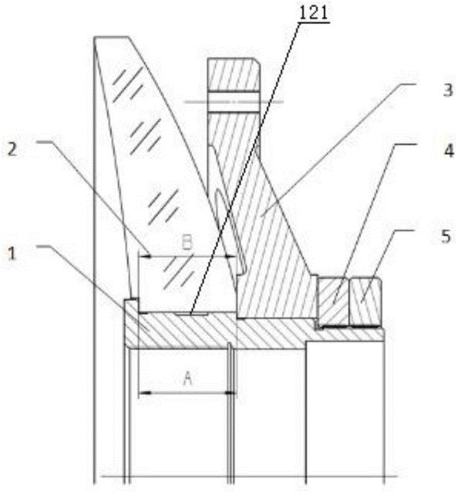
[0041] Such as Figure 4 As shown (the symmetrical structure is omitted in the figure), the small-diameter reflector support structure of the present invention includes a mandrel 1, a back plate 3, a first locking nut 4, a second locking nut 5, a pressing plate 6, a silicone pad 7 and Backing ring 8.

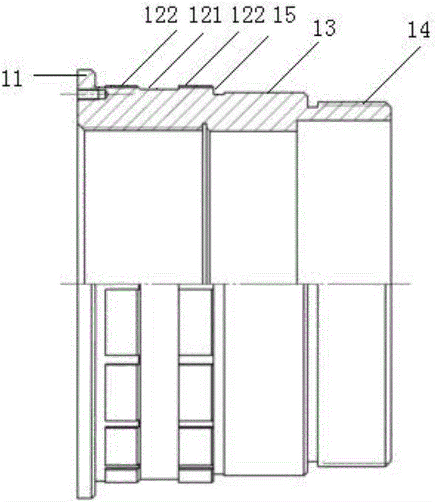
[0042] Among them, such as Figure 5 and Figure 6 As shown, the outer wall of the mandrel 1 is provided with a first endless belt 12, a second endless belt 13 and a third endless belt 14 in sequence from front to back, and the first endless belt 12, the second endless belt 13 and the third endless belt 14 The outer diameter decreases successively.

[0043]The length of the first annular band 12 is slightly less than the length of the through hole of the reflector 2; the edge circumference of the front end face of the first annular band 12 is uniformly...


PUM


Abstract

The invention relates to a small diameter reflector supporting structure which belongs to the technical field of supporting structures. The structure is invented with the object of solving the problems in the prior art that a bonded reflector supporting structure does not have uniform bonding intensity and is sensitive to temperatures. The supporting structure comprises a mandrel, a back plate, a tight pressing mechanism, a pressing plate, a silicon pad and a pad ring. The front end of the mandrel's outer wall is provided with an arc-shaped ring belt. The reflector is capable of making two-dimensional swing, axial movement, and tangential rotation around the arc-shaped ring belt. The pressing plate is fixedly arranged in the concave groove at the front end face of the mandrel. The silicon pad is fixedly arranged at the back surface of the pressing plate and presses tightly at the front ring belt of the reflector. The pad ring is sleeved on the mandrel, and both the front face and the back face of the pad ring are provided with a front boss and a back boss respectively. The bosses are in contact with the reflector's back ring belt and the front surface of the back plate. The tight pressing mechanism presses the pad ring and the back plate tightly on the mandrel shoulder. The supporting structure of the invention can ensure the accurate positioning of a reflector. And it is not affected by face shapes with different temperatures and different pitching angles. In transportation, it can also withstand slight impact and vibrations.

Description

technical field [0001] The invention belongs to the technical field of support structures, and in particular relates to a support structure for small-diameter (below 300mm) reflectors, especially suitable for supporting small-diameter meniscus-shaped lightweight reflectors. Background technique [0002] With the intensification of human space activities, a large number of space targets are distributed in the earth orbit space (space targets mainly refer to satellites, including working satellites and non-working satellites, and also include space debris, such as booster rockets entering space orbit, protection hoods and other objects, as well as various space objects entering the outer space of the earth, such as comets and asteroids), these space objects have seriously affected human space activities. Therefore, we need to know the number, distribution, orbit, and status of space targets to meet the needs of space early warning and information countermeasures. These behavi...

Claims


Application Information

Patent Timeline
Patent Type & Authority Applications(China)
IPC IPC(8): G02B7/198
CPCG02B7/198
Inventor 王槐陈宝刚赵金宇赵勇志代霜
Owner CHANGCHUN INST OF OPTICS FINE MECHANICS & PHYSICS CHINESE ACAD OF SCI
Learn More