Multifunctional combined image screen

A multi-functional combination and image screen technology, applied in the field of optical experimental equipment, can solve the problems of affecting the quality of reflected light imaging, difficult to observe the reflected image, unstable position and angle of the plane mirror, etc. Improve the effect of teaching

Inactive Publication Date: 2017-01-11
陈健
View PDF0 Cites 0 Cited by
  • Summary
  • Abstract
  • Description
  • Claims
  • Application Information

AI Technical Summary

Problems solved by technology

The instability of the position and angle of the plane mirror directly affects the imaging quality of the reflected light, making it difficult to observe the reflected image

Method used


Image

  • Multifunctional combined image screen
  • Multifunctional combined image screen

Examples


Embodiment Construction

[0011] The present invention will be further described below in conjunction with the accompanying drawings.

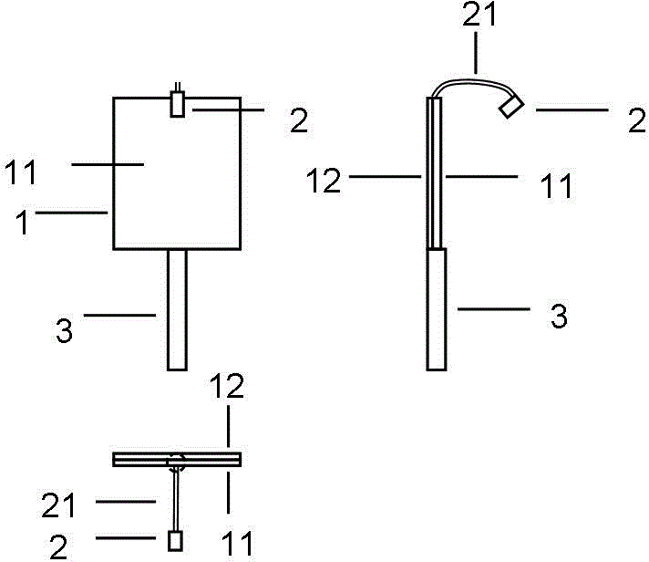
[0012] Such as figure 1 As shown, the combined image screen 1 is rectangular and is composed of a white image screen 11 and a flat mirror 12 bonded back to back. A pole 3 is arranged at the bottom of the combined image screen. The camera 2 is connected to the top center of the combined image screen 1 through arbitrarily bendable hose 21 . Camera 2 is a miniature wireless camera.

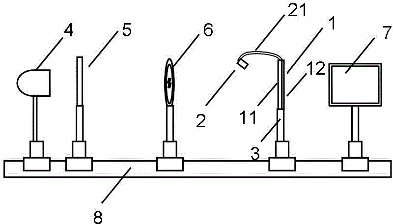
[0013] Such as figure 2 As shown, the light source 4, the object screen 5, the lens 6, the combined image screen 1, and the display 7 are successively arranged on the optical bench 8, the image screen 11 is adjusted to the image plane, and the camera 2 captures the image on the image screen 11, and the The display 7 displays and records, which is convenient for teachers to demonstrate in class and observe by students.

[0014] In the experiment of measuring the focal length of the lens ...


PUM


Abstract

The present invention discloses a multifunctional combined image screen, which comprises a combined image screen and a camera. The combined image screen is rectangular and consists of a white image screen and a flat mirror, wherein the white image screen and the flat mirror are bonded in the back-to-back manner. The camera can be bonded to the top of the combined image screen through a hose capable of being freely curved. According to the technical scheme of the invention, optical experiments are convenient in presentation and observation. Meanwhile, the teaching effect of optical experiments is further improved.

Description

technical field [0001] The invention relates to an optical experiment tool, in particular to a multifunctional combined image screen used for lens imaging experiments. Background technique [0002] The lens imaging experiment is a basic optical experiment, which measures the focal length of the lens by building a variety of optical paths, and verifies the law of lens imaging. When the teacher demonstrates the lens imaging experiment in class, because the image screen is perpendicular to the imaging optical path, it is difficult for students to see or clearly see the imaging on the image screen and judge the clarity of the image while seeing the imaging optical path. Sometimes a plane mirror is used in the experiment. For example, in the experiment of measuring the focal length of the lens by the autocollimation method, the experimenter needs to hold a plane mirror and place it behind the lens so as to reflect the light passing through the lens back to the object screen for i...

Claims


Application Information

Patent Timeline
Patent Type & Authority Applications(China)
IPC IPC(8): G09B23/22
Inventor 陈健
Owner 陈健
Why Eureka
Try Eureka