

Control method and device
A control method and external interface technology, applied in the field of communication, can solve the problem that the micro base station cannot meet the interface requirements, etc.
- Summary
- Abstract
- Description
- Claims
- Application Information
AI Technical Summary
Problems solved by technology
Method used
Image

Examples
Embodiment 1
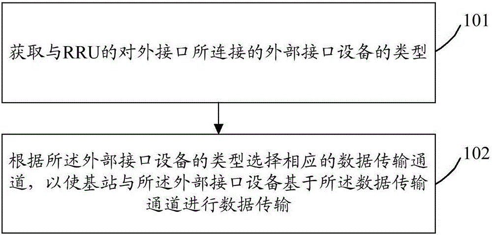
[0045] figure 1 Schematic flowchart of the control method provided by the embodiment of the present invention Figure 1 ,Such as figure 1 As shown, the control method mainly includes the following steps:
[0046] Step 101: Obtain the type of the external interface device connected to the external interface of the RRU.
[0047] Here, the external interface of the RRU may be an optical module interface, but is not limited to an optical module interface.
[0048] For example, the optical module interface may be a Small Form Pluggable (SFP, Small Form Pluggable) optical module, an SFP+ optical module, etc., but is not limited to the SFP optical module and the SFP+ optical module.
[0049] Preferably, the obtaining the type of the external interface device connected to the external interface of the RRU may include:
[0050] Read the identification number of the external interface device connected to the external interface of the RRU;
[0051] The type of the external interface...
Embodiment 2
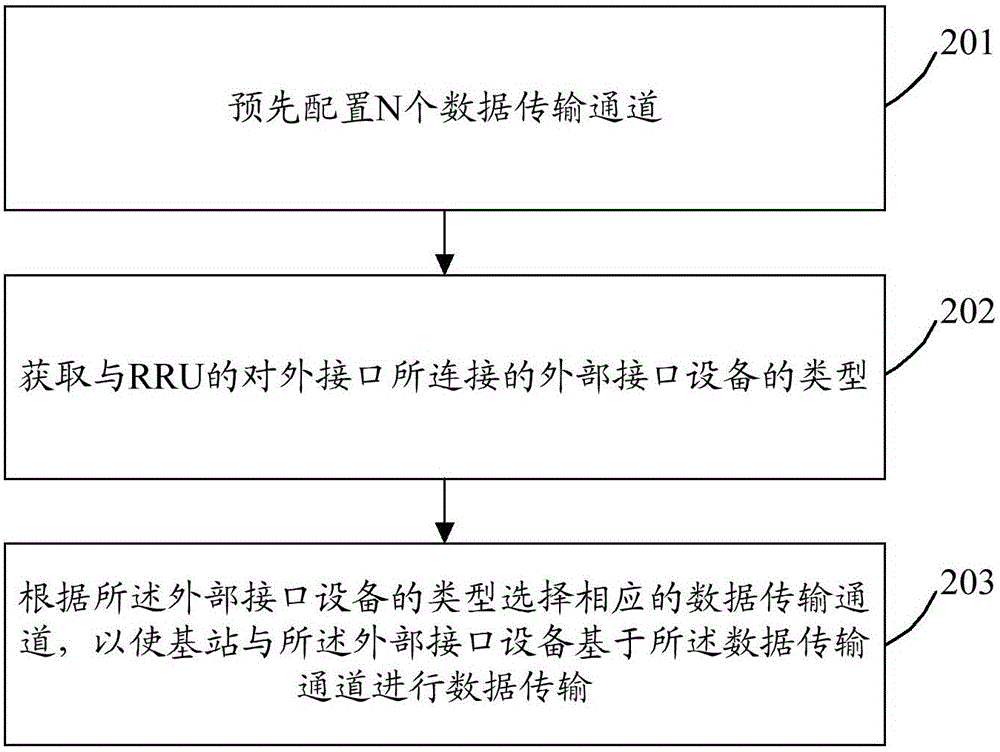
[0085] figure 2 Schematic flowchart of the control method provided by the embodiment of the present invention Figure II ,Such as figure 2 As shown, the control method mainly includes the following steps:
[0086] Step 201: Pre-configure N data transmission channels.
[0087] Wherein, each data transmission channel corresponds to a type of external interface device; N is a positive integer greater than or equal to 2.
[0088] For example, N=4, the first data transmission channel corresponds to the Ethernet interface, the second data transmission channel corresponds to the serial port interface, the third data transmission channel corresponds to the USB interface, and the fourth data transmission channel corresponds to the optical fiber interface .
[0089] Wherein, the data channel of the optical fiber interface is a default data transmission channel. That is, if the type of external interface device connected cannot be identified, the data channel of the optical fiber ...
Embodiment 3
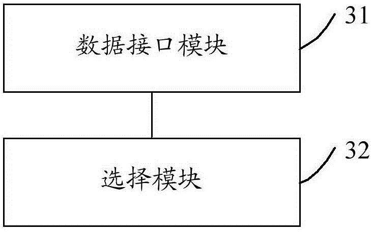
[0109] image 3 Schematic diagram of the composition and structure of the control device provided by the embodiment of the present invention Figure 1 ,Such as image 3 As shown, the device includes a data interface module 31 and a selection module 32; wherein,
[0110] The data interface module 31 is configured to acquire the type of the external interface device connected to the external interface of the RRU;
[0111] The selection module 32 is configured to select a corresponding data transmission channel according to the type of the external interface device, so that the base station and the external interface device perform data transmission based on the data transmission channel.
[0112] Here, the external interface of the RRU may be an optical module interface, but is not limited to an optical module interface.
[0113] For example, the optical module interface may be an optical module, an SFP+ optical module, and the like.
[0114] Here, the external interface dev...
PUM
 Abstract
Description
Claims
Application Information