Method of realizing dynamic frame function for television, television and television system

A technology for televisions and picture frames, applied in the field of television, can solve problems such as the inability to provide the artistic, entertainment and educational functions of art galleries, the limitation of the depth, breadth and refinement of the picture, and the lack of interest and attention of consumers. , to achieve the effect of improving artistic literacy and quality of life, cultivating temperament, and beautifying home

Inactive Publication Date: 2017-01-11
深圳市锦和禄文化传播有限公司
View PDF8 Cites 9 Cited by
  • Summary
  • Abstract
  • Description
  • Claims
  • Application Information

AI Technical Summary

Problems solved by technology

Although a small number of TVs can play a few preset limited screens during standby, the depth, breadth and fineness of the screens are all limited by the internal storage space of the TV. Therefore, the TV only has the basic screen saver function, and the It cannot provide artistic, entertaining and educational functions at the level of art museums, and it is not enough to arouse consumers' interest and attention
[0003] Although the above-mentioned storage space limitation may be solved by an external device (such as a USB or HDMI disk), a certain degree of technical background is required to perform the interface and settings, so few consumers are willing to spend such a lot of trouble for a trivial screen saver , so the generalization of the function is limited
[0004] In addition, some standby solutions are based on TV set-top boxes that can provide images. However, no matter how much content is available, the fatal flaw is that the broadcast right of the set-top box lies with the TV. Once the TV is turned off or on standby, the service of the set-top box must be stopped.

Method used


Image

  • Method of realizing dynamic frame function for television, television and television system
  • Method of realizing dynamic frame function for television, television and television system
  • Method of realizing dynamic frame function for television, television and television system

Examples


Embodiment Construction

[0034] In order to have a clearer understanding of the technical features, purposes and effects of the present invention, the specific implementation manners of the present invention will now be described in detail with reference to the accompanying drawings.

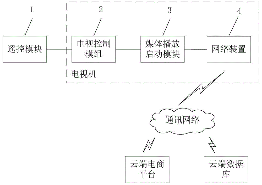
[0035] refer to figure 1 , is a schematic structural diagram of a preferred embodiment of the television system of the present invention;

[0036] The TV system of the present invention includes a remote control module 1 and a TV set, wherein the TV set includes a TV control module 2, a multimedia playback start-up module 3 set in the TV firmware or new firmware, and a built-in or external network means 4, wherein:

[0037] Remote control module 1: used to send various commands to the TV control module 2;

[0038] The TV control module 2: used to send a display control instruction to the media playback activation module 3 to transfer the screen control of the TV display interface to the media playback activation modul...


PUM


Abstract

The invention discloses a method of realizing a dynamic frame function for a television, the television and a television system. The television comprises a television control module, a media playback starting module arranged in television software or newly-added firmware and a network device. The method comprises steps: a) after the television control module in a power-on state receives a power-off instruction inputted by a remote control module, a display control right instruction is sent to the media playback starting module, and the television control module enters a standby state; b) after the media playback starting module receives the display control right instruction, a cloud-end database on the internet is connected via the network device, wherein the cloud-end database stores digital archives for background music and arc works pictures; and c) the media playback starting module acquires the digital archives, and a display interface is controlled to play the arc works pictures and the background music according to a preset sequence. Due to the display picture in the standby state, the dynamic digital frame function can be realized for the television, the resources are acquired from the cloud-end database, and limitations from local storage space do not exist.

Description

technical field [0001] The invention relates to the field of television, in particular to a method for realizing a dynamic picture frame function of a television, a television and a television system. Background technique [0002] Present TV sets only possess the TV function. Common TVs generally include two states of power-on and power-off. Considering that the user does not watch TV and does not want to turn on the next time, some TVs also provide a standby state. In the prior art, Most of them just provide a monotonous black, gray or blue screen in standby. Although a small number of TVs can play a few preset limited screens during standby, the depth, breadth and fineness of the screens are all limited by the internal storage space of the TV. Therefore, the TV only has the basic screen saver function, and the It cannot provide the artistic, entertaining and educational functions of the museum level, let alone arouse the interest and attention of consumers. [0003] Alth...

Claims


Application Information

Patent Timeline
Patent Type & Authority Applications(China)
IPC IPC(8): H04N21/478H04N21/422H04N21/443H04N21/431H04N21/81
Inventor 苏堤惠宣
Owner 深圳市锦和禄文化传播有限公司
Why Eureka
Try Eureka