Injection molding equipment

A technology of injection molding equipment and injection materials, which is applied in the field of injection molding equipment, can solve problems such as breakdown motors, high cost of monostable circuits, and increase the cost of injection molding equipment, so as to reduce costs and improve market competitiveness.

Inactive Publication Date: 2017-01-18
SHENZHEN BEIYOUTONG NEW ENERGY TECH DEV CO LTD
View PDF3 Cites 3 Cited by
  • Summary
  • Abstract
  • Description
  • Claims
  • Application Information

AI Technical Summary

Problems solved by technology

[0003] In the existing injection molding equipment, the motor needs to control the opening and closing of the movable mold and the fixed mold, and because the motor needs to be reversed, it is easy to cause a reverse voltage to break down the coil of the motor when the motor switches voltage, thereby reducing the The reliability of injection molding equipment; not only that, when the injection molding equipment is working, it needs an internal monostable circuit to ensure its stable operation, and the cost of the monostable circuit is high, which increases the cost of injection molding equipment and reduces its market competitiveness

Method used


Image

  • Injection molding equipment
  • Injection molding equipment

Examples


Embodiment Construction

[0023] The present invention will now be described in further detail with reference to the drawings. These drawings are all simplified schematic diagrams, which merely illustrate the basic structure of the present invention in a schematic manner, so they only show the structures related to the present invention.

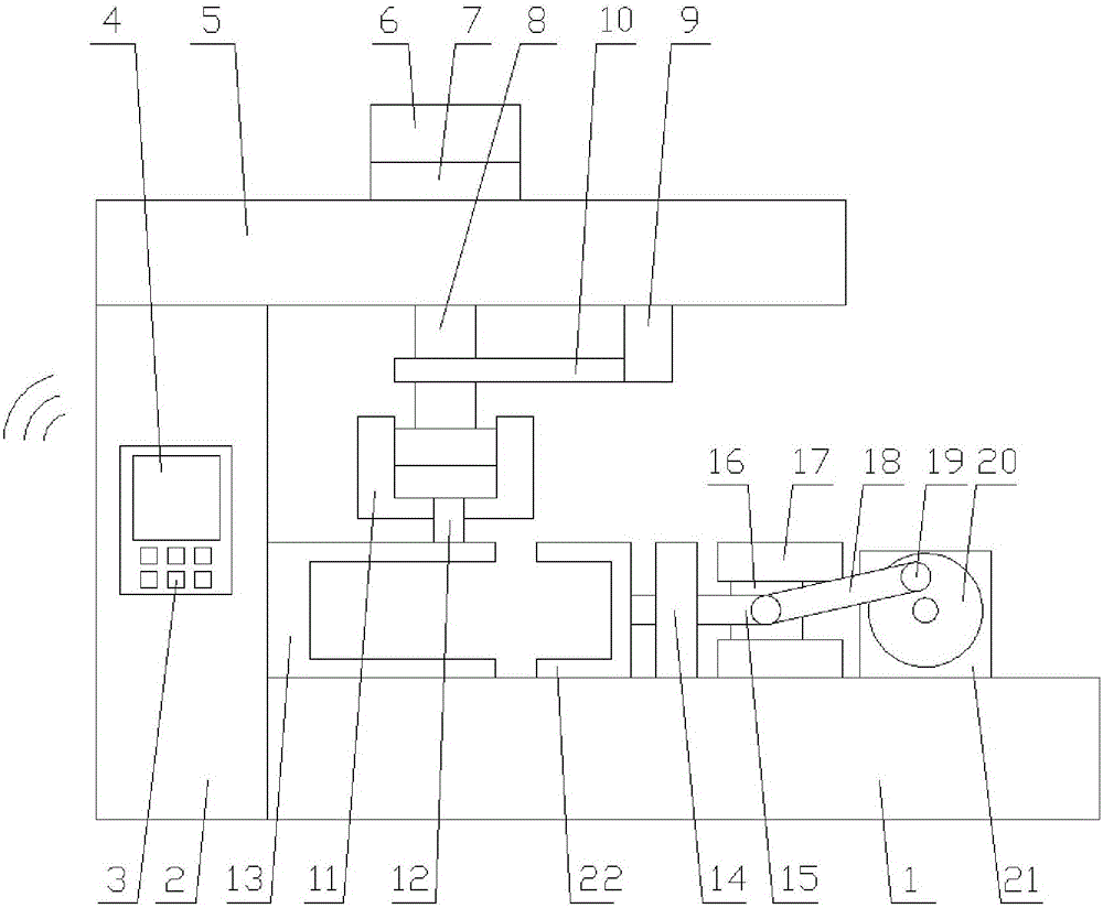
[0024] Such as figure 1 with figure 2 As shown, an injection molding equipment includes a base 1, a pillar 2 arranged on one side of the base 1, a beam 5 arranged on the top end of the pillar 2, and an injection molding mechanism arranged on the base 1;

[0025] The injection molding mechanism includes an injection assembly arranged on the cross beam 5 and an opening and closing mold assembly arranged on the base 1, the injection assembly being in communication with the opening and closing mold assembly;

[0026] The mold opening and closing assembly includes a fixed mold 13, a movable mold 22, and a driving unit. The fixed mold 13 is fixed above the base 1, and the drivi...


PUM


Abstract

The invention relates to injection molding equipment. The injection molding equipment comprises a base, a support pillar, a cross beam and an injection molding mechanism, wherein the support pillar is arranged on one side of the base, the cross beam is arranged on the top end of the support pillar, and the injection molding mechanism is arranged on the base; the injection molding mechanism comprises a material injection assembly arranged on the cross beam and a mold opening and closing assembly arranged on the base, and the material injection assembly communicates with the mold opening and closing assembly; and the mold opening and closing assembly comprises a fixed mold, a movable mold and a driving unit, the fixed mold is fixed above the base, and the driving unit is in transmission connection with the movable mold. According to the injection molding equipment, firstly, a driving wheel is controlled to rotate by virtue of a driving motor, subsequently, a sliding block is controlled to move in a guide rail by the driving wheel by virtue of a connecting rod, so that a push-pull rod can be controlled to push and pull the movable mold, and additionally, the push-pull rod is limited by virtue of a limiting post, so that the push-pull rod horizontally moves; additionally, one-side triggering is adopted in a monostable circuit, so that a trigger circuit of a first transistor base is omitted, the cost of the circuit is reduced, and the market competitiveness of the injection molding equipment is increased.

Description

Technical field [0001] The invention relates to an injection molding equipment. Background technique [0002] Injection molding equipment is also known as injection molding machine or injection machine. It is the main molding equipment that uses plastic molding dies to make thermoplastic or thermoset plastics into various shapes of plastic products. Divided into vertical, horizontal and all-electric. The injection molding machine can heat the plastic and apply high pressure to the molten plastic to make it eject and fill the mold cavity. [0003] In the existing injection molding equipment, a motor is required to control the opening and closing of the moving mold and the fixed mold, and because the motor needs to be reversed, it is easy to cause the reverse voltage to break down the motor coil when the motor switches the voltage, thereby reducing The reliability of the injection molding equipment; not only that, when the injection molding equipment is working, the internal monos...

Claims


Application Information

Patent Timeline
Patent Type & Authority Applications(China)
IPC IPC(8): B29C45/17
CPCB29C45/17B29C2045/1792
Inventor 蒙泽喜
Owner SHENZHEN BEIYOUTONG NEW ENERGY TECH DEV CO LTD
Why Eureka
Try Eureka