A method of manufacturing a fin and flat tube assembly for a heat exchanger

A heat exchanger and a manufacturing method technology, applied in heat exchange equipment and other directions, can solve the problems of low fin strength, insufficient fin strength, fin shape damage, etc., and achieve high strength, wide application range and high production efficiency. Effect

Active Publication Date: 2018-02-02
SDAAC AUTOMOTIVE AIR CONDITIONING SYST CO LTD SHANGHAI
View PDF7 Cites 0 Cited by
  • Summary
  • Abstract
  • Description
  • Claims
  • Application Information

AI Technical Summary

Problems solved by technology

[0002] At present, the fins used in the heat exchanger are all made of aluminum foil, which is thinner and the strength of the formed fins is lower
And after the fins are inserted into the heat dissipation flat tube, there is not enough space to apply flux to make it adhere to the surface of the aluminum foil material, so when welding, the fins and the heat dissipation flat tube are poorly welded
[0003] At the same time, due to the insufficient strength of the fins, the fins need to be divided and inserted into the flat tubes in sections, and the efficiency of the installation process is low
[0004] If the above method of dividing the fins to ensure their strength is adopted, it will easily lead to deformation and blockage at both ends of the fins, and the original shape of the fins will be damaged.

Method used


Image

  • A method of manufacturing a fin and flat tube assembly for a heat exchanger
  • A method of manufacturing a fin and flat tube assembly for a heat exchanger
  • A method of manufacturing a fin and flat tube assembly for a heat exchanger

Examples


Embodiment Construction

[0046] The advantages of the present invention will be further elaborated below in conjunction with the accompanying drawings and specific embodiments.

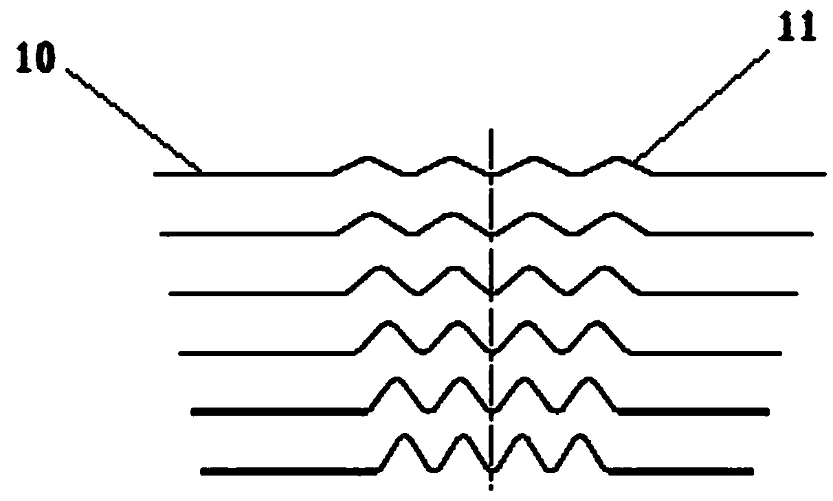
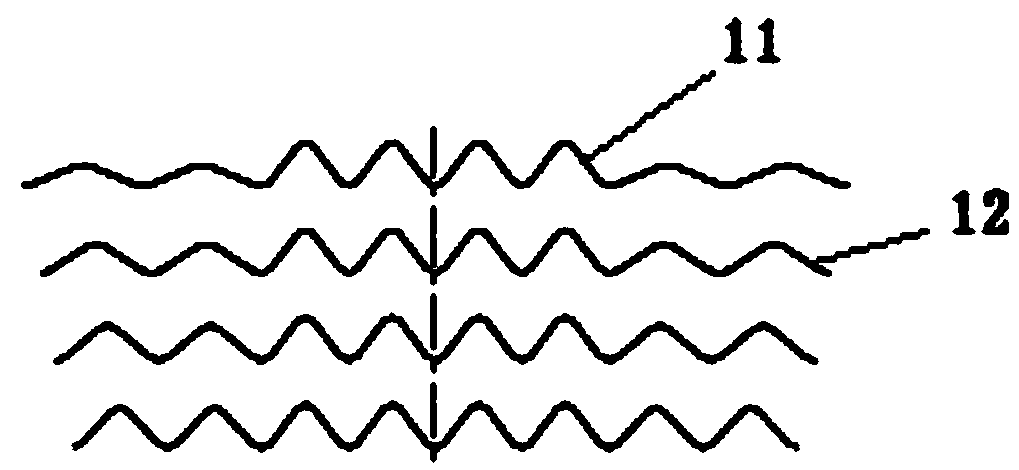
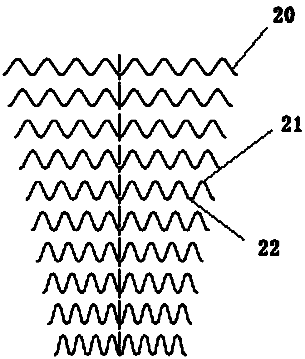
[0047] refer to Figure 1-5 , respectively showing the method of manufacturing fins for heat exchangers, specifically:

[0048] - Step 1: If figure 1 As shown, the user obtains a metal substrate 10 as the basis for manufacturing flat tubes. The metal substrate 10 can be aluminum foil, metal strip (composite layer), etc., and is first straightened to meet the continuous and seamless surface of the final formed fin. bumps or pits. Then the metal base material 10 is put into a mold, and the middle part of the metal base material 10 is rolled. The rolled metal base material 10 has a pair of first wavy protrusions 11 formed therein. Specifically, for example, four groups of protrusion units are formed by repeatedly rolling the middle of the metal base material 10 on both ends of the metal base material 10 , each protrusion unit...


PUM


Abstract

A method for manufacturing a fin and flat tube assembly used in a heat exchanger, comprising following steps: step 1: taking a metal substrate (10) and straightening same, and rolling the middle part of the metal substrate (10) to form paired first wave-like protrusions (11); step 2: separately rolling parts from both ends of the metal substrate (10) to the first wave-like protrusions (11), to form paired second wave-like protrusions (12); step 3: rolling the first wave-like protrusions (11) and the second wave-like protrusions (12) to make wave pitches and amplitudes of the first wave-like protrusions (11) and the second wave-like protrusions (12) the same, so as to form a wave-like fin (20); step 4: rolling each of peak portions (21) and trough portions (22) of the wave-like fin (20) and shaping the peak portion (21) and the trough portion (22) into rectangles with rounded corners; and step 5: rolling each of peak and trough such that the peak portions (21) and the trough portions (22) are inwardly formed.

Description

technical field [0001] The invention relates to the field of heat exchanger equipment, in particular to a manufacturing method for a heat exchanger fin and flat tube assembly. Background technique [0002] At present, the fins used in the heat exchanger are all made of aluminum foil, which is relatively thin and the strength of the formed fins is low. And after the fins are inserted into the heat dissipation flat tubes, there is not enough space to smear flux to make it adhere to the surface of the aluminum foil material, so when welding, the fins and the heat dissipation flat tubes are poorly welded. [0003] At the same time, due to the insufficient strength of the fins, the fins need to be divided and inserted into the flat tubes in sections, and the efficiency of the installation process of the equipment is low. [0004] If the above method of dividing the fins to ensure their strength is adopted, it will easily lead to deformation and blockage at both ends of the fins,...

Claims


Application Information

Patent Timeline
Patent Type & Authority Patents(China)
IPC IPC(8): B21D13/04B21D53/04B23P15/26
CPCB21D13/04
Inventor 于江
Owner SDAAC AUTOMOTIVE AIR CONDITIONING SYST CO LTD SHANGHAI
Why Eureka
Try Eureka