
Lifting carrying device

A technology of handling device and lifting platform, which is applied in the direction of power device, electric power device, circuit or fluid pipeline, etc. It can solve the problems of difficult positioning, inaccurate and fast battery replacement, long charging time, etc.

Active Publication Date: 2017-01-25
SHENZHEN JINGZHI MACHINE
View PDF7 Cites 23 Cited by
  • Summary
  • Abstract
  • Description
  • Claims
  • Application Information

AI Technical Summary

Problems solved by technology

[0002] With the rapid development of electric vehicles, problems such as high battery cost, low battery life, and long charging time need to be solved urgently
Replacing the battery for an electric vehicle is an effective way to solve the battery problem. The battery of an electric vehicle is generally installed at the bottom of the electric vehicle, and mechanical equipment for moving the battery is required for automatic replacement. replacement battery

Method used


Image

  • Lifting carrying device
  • Lifting carrying device
  • Lifting carrying device

Examples


Embodiment Construction

[0035] In order to facilitate the understanding of the present invention, the lifting and conveying device will be described more fully below with reference to the relevant drawings. A preferred embodiment of the lifting and handling device is shown in the accompanying drawings. However, the lift handling device can be implemented in many different forms and is not limited to the embodiments described herein. On the contrary, the purpose of providing these embodiments is to make the disclosure of the lifting and conveying device more thorough and comprehensive.

[0036] Unless otherwise defined, all technical and scientific terms used herein have the same meaning as commonly understood by one of ordinary skill in the technical field of the invention. The terminology used herein in the description of the lifting and conveying device is only for the purpose of describing specific embodiments, and is not intended to limit the present invention.

[0037] Such as figure 1 , fi...


PUM


Abstract

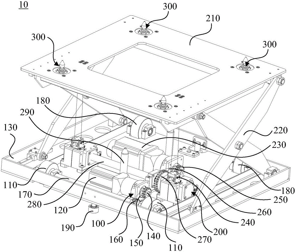
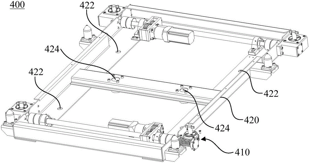
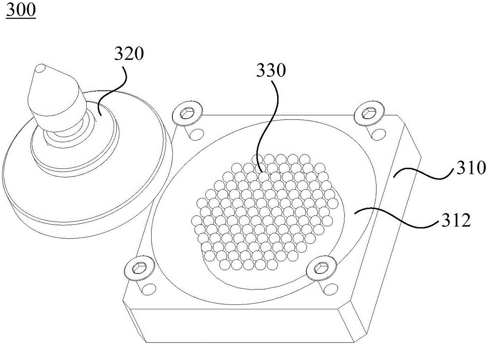
The invention relates to a lifting carrying device. The lifting carrying device comprises a walking mechanism, a lifting mechanism, a floating mechanism and an unlocking mechanism; the floating mechanism comprises a base, a positioning part and balls, the base is fixedly connected to a lifting platform, the positioning part can slide on the bottom surface of a groove, and the balls are located between the positioning part and the bottom surface of the groove; the unlocking mechanism comprises an unlocking assembly and a floating table, positioning holes are formed in the floating table, and the positioning part is clamped on the floating table through the positioning holes. Through the walking mechanism, the lifting carrying device is controlled to walk to a preset position, the lifting mechanism lifts carried equipment such as batteries of electric automobiles to a preset height, and the floating table is generally used for bearing the carried equipment; the positioning part of the floating mechanism can move on the plane within a small range to carry out micro-adjustment on the position where the floating table is located, in this way, the unlocking assembly of the floating mechanism can accurately position the corresponding position, and then the carried equipment can be accurately and rapidly unlocked and replaced.

Description

technical field [0001] The invention relates to the technical field of mechanical transportation, in particular to a lifting transportation device. Background technique [0002] With the rapid development of electric vehicles, problems such as high battery cost, low battery life, and long charging time need to be solved urgently. Replacing the battery for an electric vehicle is an effective way to solve the battery problem. The battery of an electric vehicle is generally installed at the bottom of the electric vehicle, and mechanical equipment for moving the battery is required for automatic replacement. to replace the battery. Contents of the invention [0003] Based on this, it is necessary to provide a lifting and conveying device capable of accurate positioning to solve the above problems. [0004] A lifting and conveying device, including a traveling mechanism, a lifting mechanism, a floating mechanism and an unlocking mechanism; [0005] The traveling mechanism in...

Claims


Application Information

Patent Timeline
IPC IPC(8): B60S5/06
Inventor 王伟梁虎黄拾龙
Owner SHENZHEN JINGZHI MACHINE
Learn More