Supercharge Your Innovation With Domain-Expert AI Agents!

Pneumatic control mechanism and control method for roller groove ironing connection

A technology of pneumatic control and roller groove, which is applied in the field of flat fabric ironing, and can solve the problems of single-group equipment maintenance and single-group equipment that cannot be used and operated independently

Active Publication Date: 2018-10-09
SHANGHAI SAILSTAR MACHINERY GRP
View PDF6 Cites 2 Cited by
  • Summary
  • Abstract
  • Description
  • Claims
  • Application Information

AI Technical Summary

Problems solved by technology

[0004] The existing roller groove ironing mechanism only adds a set of fixed connecting brackets between the roller ironing and groove ironing. A single set of equipment cannot be used and operated independently, and it is impossible to maintain a single set of equipment without disassembling the connecting mechanism. maintainance

Method used


Image

  • Pneumatic control mechanism and control method for roller groove ironing connection

Examples


Embodiment Construction

[0022] The present invention will be described in detail below in conjunction with the accompanying drawings and embodiments.

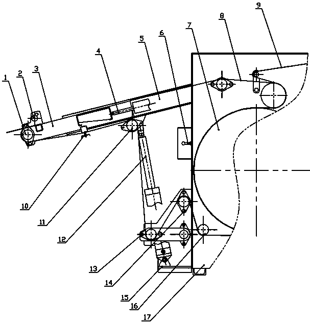
[0023] see figure 1 , the present invention provides a pneumatic control mechanism for the connection of roller groove ironing, which is mainly composed of a main support connecting frame 5, a cloth output shaft 1, a cloth pressing shaft 2, an ironing roller 7, a driving ironing belt 8, and a guide belt 9. Roll frame 17 after roller ironing, telescopic support 3, telescopic cylinder 4, control handle 6, spacer pin 10, guide shaft I 11, lifting cylinder 12, anti-drop swing bar 13, guide shaft II 14, lifting cylinder Bracket 15 and guide shaft III 16 form.

[0024] The front end of the main support connecting frame 5 is provided with a telescopic support 3, and the telescopic support 3 is connected to the telescopic cylinder 4, and the lower air inlet of the telescopic cylinder 4 is provided with an air inlet valve. The bottom of the main support adap...


PUM


Abstract

The invention relates to a pneumatic control mechanism for linking up a roller type ironing machine and a groove type ironing machine and a control method. A telescopic support is arranged at the front end of a main supporting link-up frame, and is connected with a telescoping air cylinder, wherein a band isolating pin and a guiding shaft I are mounted at the bottom of the main supporting link-up frame; a lifting air cylinder, a band falling preventing swing link and a guiding shaft II are mounted on a lifting air cylinder bracket; a piston rod of the lifting air cylinder drives the main supporting link-up frame and the telescopic support to rise; the band falling preventing swing link is connected with a driving ironing band; a control handle manually controls the pneumatic control mechanism, and linen is conveyed to the pneumatic control mechanism from an ironing roller of the roller type ironing machine under the traction of the driving ironing band and a leading band. In order to give full play to advantages of the two kinds of ironing machines, i.e., the roller type ironing machine and the groove type ironing machine, the link-up mechanism provided by the invention has the advantages that the two kinds of ironing machines are used under the same working condition, through being matched with a pneumatic control unit, during the maintenance of an ironing groove of the groove type ironing machine, the normal use of the other single unit is not affected when one single unit is in failure.

Description

technical field [0001] The invention belongs to the technical field of flat fabric ironing, and relates to a roller groove ironing machine in industrial washing equipment and other roller ironing or groove ironing equipment that needs to be connected, in particular to a pneumatic control mechanism for the roller groove ironing connection and Control Method. Background technique [0002] As an ironing equipment in the industrial washing industry, it is widely used in hotels, hospitals and various social washing factories together with other washing equipment; it is mainly used for drying and ironing flat fabrics such as bed sheets and quilt covers, and is in the washing process the end. [0003] This type of ironing equipment can be divided into roller ironing machine and groove ironing machine according to its structure and ironing method. These two kinds of equipment have their own advantages and disadvantages in use. [0004] The existing roller groove ironing mechanism ...

Claims


Application Information

Patent Timeline
Patent Type & Authority Patents(China)
IPC IPC(8): D06F65/06
CPCD06F65/06
Inventor 张亮亮陈赛赛徐勤龙刘晓东葛荣泉
Owner SHANGHAI SAILSTAR MACHINERY GRP
Features
  • R&D
  • Intellectual Property
  • Life Sciences
  • Materials
  • Tech Scout
  • Unparalleled Data Quality
  • Higher Quality Content
  • 60% Fewer Hallucinations
Learn More