Rotary compressor

A rotary compressor and compressor technology, applied to rotary piston/oscillating piston pump components, mechanical equipment, machines/engines, etc., can solve the problem of poor air suction at 90' of the pump body and affect the performance of the compressor, etc. question

Active Publication Date: 2017-01-25
重庆凌达压缩机有限公司
View PDF8 Cites 1 Cited by
  • Summary
  • Abstract
  • Description
  • Claims
  • Application Information

AI Technical Summary

Problems solved by technology

When the compressor is working, the balance weight rotates at a high speed, agitating the gas in the

Method used


Image

  • Rotary compressor
  • Rotary compressor
  • Rotary compressor

Examples


Embodiment Construction

[0044] The present invention will be described in further detail below in conjunction with the accompanying drawings and specific embodiments, but not as a limitation of the present invention.

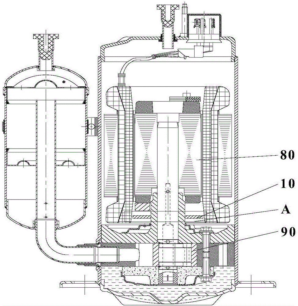
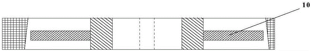
[0045] like figure 2 and image 3 As shown, the embodiment of the present invention provides a rotary compressor, including a rotor 80 and a pump body 90, the rotary compressor also includes a partition 10 for separating the rotor 80 and the pump body 90, and the partition 10 is arranged on the rotor 80 and pump body 90 between.

[0046] The separator 10 is set to separate the rotor 80 from the pump body 90, which can prevent the impact of the exhaust gas from the pump body 90 on the rotor 80, prevent the exhaust gas from the pump body 90 from impacting the rotor 80, and avoid the axial runout of the crankshaft and the rotor 80. Thereby reducing or avoiding the generation of noise and achieving the purpose of eliminating abnormal sound. The above partition 10 can be made of metal o...


PUM


Abstract

The invention discloses a rotary compressor, which comprises a rotor and a pump body. The rotary compressor further comprises a partition used for separating the rotor from the pump body, and the partition is arranged between the rotor and the pump body. By virtue of applying the technical scheme, the partition is arranged so as to separate the rotor from the pump body and prevent exhaust of the pump body from impacting the rotor, so that the rotor is protected from being impacted by exhaust of the pump body, axial runout between a crank shaft and the rotor is avoided, further noises are reduced or avoided, and the purpose of eliminating abnormal noises is achieved.

Description

technical field [0001] The invention relates to the field of compressors and air conditioners, in particular to a rotary compressor. Background technique [0002] like figure 1 As shown, when the rotary compressor in the prior art is in operation, the exhaust gas from the pump body 90' will impact the rotor 80', causing the crankshaft and the rotor 80' to bounce axially and generate noise. For the low back pressure compressor, the pump body 90' sucks air from the upper flange, and the suction port is close to the balance weight position of the rotor 80'. When the compressor is working, the balance weight rotates at a high speed, agitating the gas in the nearby area, making the pump body 90' poor in suction and affecting the performance of the compressor. Contents of the invention [0003] An embodiment of the present invention provides a rotary compressor, which achieves the purpose of preventing the exhaust gas from the pump body from impacting the rotor. [0004] In o...

Claims


Application Information

Patent Timeline
IPC IPC(8): F04C29/00
CPCF04C29/00F04C2240/80
Inventor 刘达炜范少稳谢利昌
Owner 重庆凌达压缩机有限公司
Why Eureka
Try Eureka