
Precise walking device for extrapolation method correction of antenna/field probe and correcting system

A walking device and extrapolation technology, which is applied in the direction of measuring devices, instruments, and measuring electrical variables, can solve the problems of field errors and near-field measurement errors, and achieve the effects of simple and compact structure, high precision, and easy operation

Pending Publication Date: 2017-01-25
GUANGZHOU CEPREI CALIBRATION & TESTING CENT SERVICE
View PDF8 Cites 2 Cited by
  • Summary
  • Abstract
  • Description
  • Claims
  • Application Information

AI Technical Summary

Problems solved by technology

[0002] The calibration of the microwave antenna gain / coefficient and the calibration factor of the microwave field probe is generally carried out in the microwave anechoic chamber. Because the microwave anechoic chamber absorbing material is not ideal, there is wall emission, and the combination of reflected wave and direct wave makes the test space form a standing wave. This is not For an ideal uniform plane wave, the field strength at the receiving point will be different from the theoretical field strength, which will cause site errors
[0003] In addition, antenna calibration and field probe calibration are carried out in the near field with a limited distance (1 ~ 3) m, using approximate formulas and coupling between antennas will introduce near field measurement errors

Method used


Image

  • Precise walking device for extrapolation method correction of antenna/field probe and correcting system
  • Precise walking device for extrapolation method correction of antenna/field probe and correcting system
  • Precise walking device for extrapolation method correction of antenna/field probe and correcting system

Examples


Embodiment Construction

[0021] The specific embodiments of the present invention will be further described below in conjunction with the accompanying drawings.

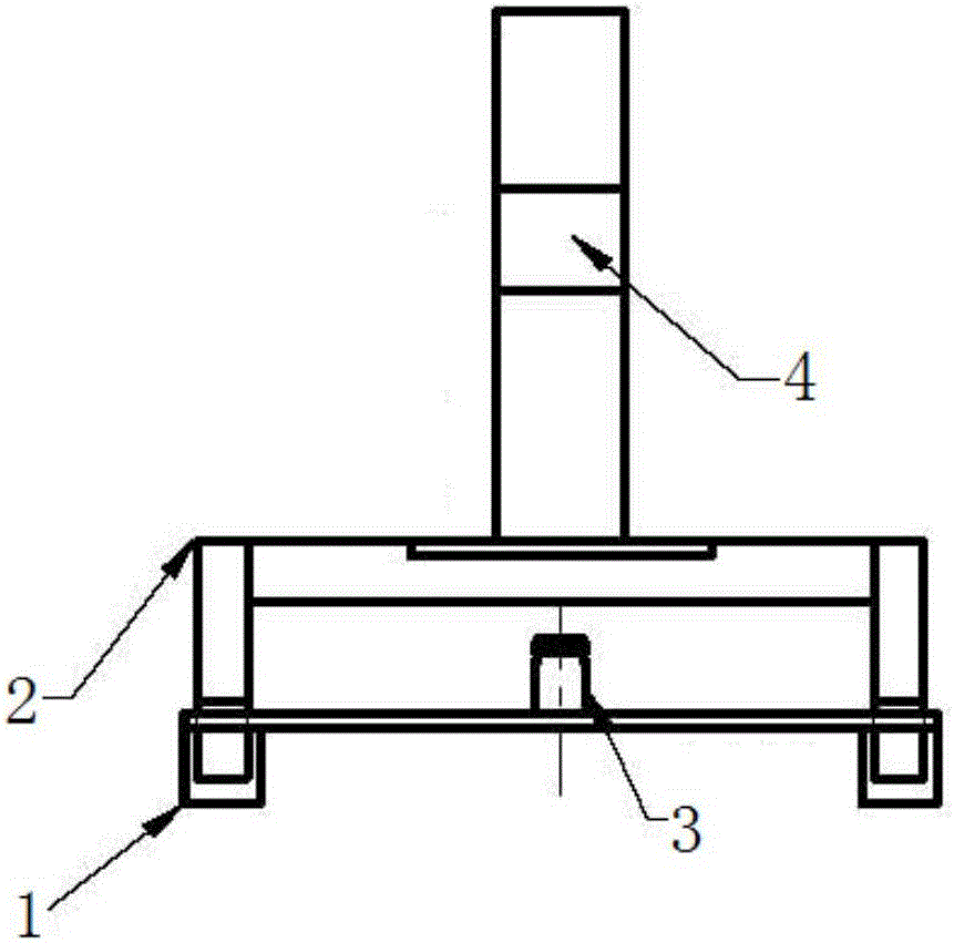
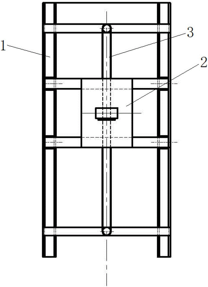
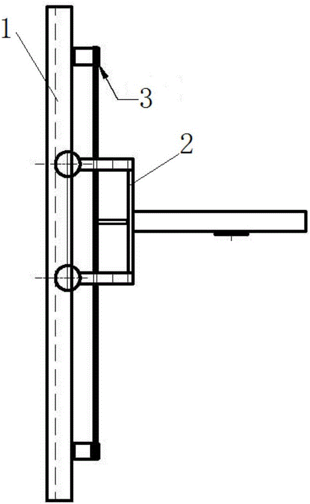
[0022] The present invention is realized like this, as Figure 1-3 As shown, the precision traveling device includes a guide rail 1, a traveling mechanism 2 arranged on the guide rail 1, and a driving mechanism 3 for driving the traveling mechanism 2 to move along the guide rail 1; the upper part of the traveling mechanism 2 is fixed with a mirror for calibration 4. The present invention uses the driving mechanism 3 to drive the traveling mechanism 2 to move along the guide rail 1, thereby driving the reflector 4 on the traveling mechanism 2 to move, so that the guide rail 1 can achieve good straightness and equal height, thereby ensuring that the mirror 4 Walk precisely along the set track.

[0023] In order to improve the reliability of the structure and the convenience of installation and use, the present invention has carried out struct...


PUM


Abstract

The invention relates to a precise walking device for extrapolation method correction of an antenna / field probe and a correcting system. The precise walking device comprises guide rails, a walking mechanism and a driving mechanism, wherein the walking mechanism is arranged on the guide rails, and the driving mechanism is used for driving the walking mechanism to move along the guide rails; and a reflecting mirror for correcting is fixed at the upper part of the walking mechanism. The correcting system comprises the precise walking device for extrapolation method correction of the antenna / field probe, a tested antenna / probe and a double-frequency laser interferometer, wherein the tested antenna / probe is fixed on a support rod, and the double-frequency laser interferometer is fixed on an emitting antenna and is matched with the precise walking device and is arranged opposite to the reflecting mirror in the precise walking device. According to the precise walking device, the requirements on the extrapolation method correction of high-precision antennas and field probes are met, the structure is simple, compact, reliable and stable, and the precise walking device further has the characteristics of being simple and convenient to operate, high in precision and the like and can be widely applied to the occasions of correction, testing and the like of microwave antennas and microwave field probes.

Description

technical field [0001] The invention relates to antenna / field probe calibration technology, in particular to a precision walking device and a calibration system for antenna / field probe extrapolation calibration. Background technique [0002] The calibration of the microwave antenna gain / coefficient and the calibration factor of the microwave field probe is generally carried out in the microwave anechoic chamber. Because the microwave anechoic chamber absorbing material is not ideal, there is wall emission, and the combination of reflected wave and direct wave makes the test space form a standing wave. This is not For an ideal uniform plane wave, the field strength at the receiving point will be different from the theoretical field strength, which will cause site errors. [0003] In addition, antenna calibration and field probe calibration are carried out in the near field with a limited distance (1-3) m, and the use of approximate formulas and coupling between antennas will ...

Claims


Application Information

Patent Timeline
Patent Type & Authority Applications(China)
IPC IPC(8): G01R35/00
CPCG01R35/005
Inventor 梁琼崇
Owner GUANGZHOU CEPREI CALIBRATION & TESTING CENT SERVICE
Learn More