Winding needle calibration device
A calibration device and needle rolling technology, applied in the direction of angle/taper measurement, can solve the problems of long time, low measurement efficiency, inconvenient use, etc., and achieve the effect of reducing the finishing area, improving the measurement accuracy, and reducing the production cost
- Summary
- Abstract
- Description
- Claims
- Application Information
AI Technical Summary
Problems solved by technology
Method used
Image
Examples
no. 1 example
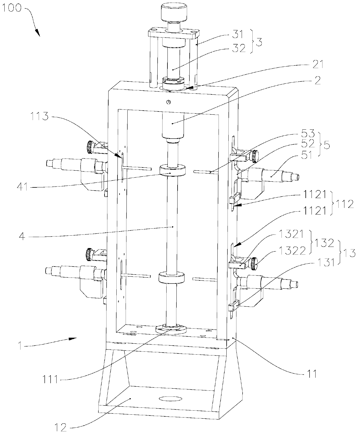
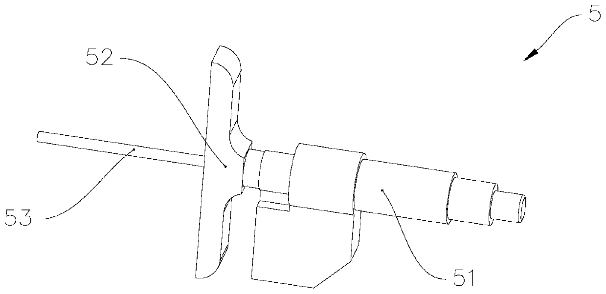
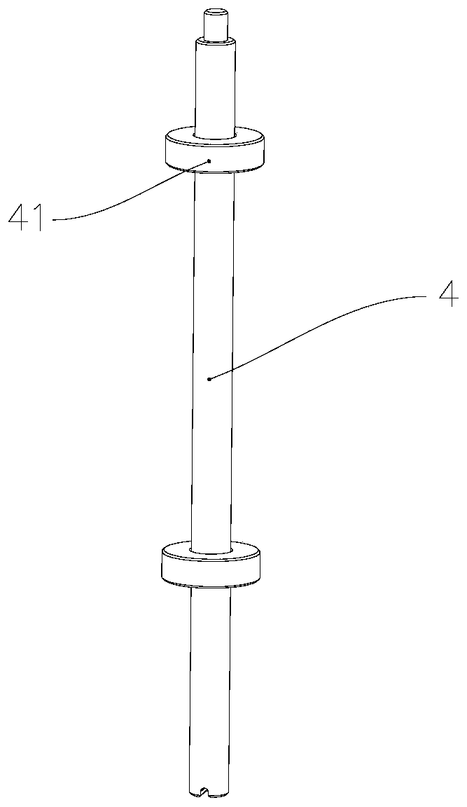
[0032] refer to figure 1 , The needle roll calibration device 100 includes a fixed seat 1, a sliding sleeve 2, a drive unit 3, a calibration shaft 4 and a measuring tool.
[0033] The fixed seat 1 includes a frame body 11 and a base 12, the frame body 11 is installed on the base 12, and a mounting hole is provided on a side of the frame body 11 close to the base 12, and the mounting hole is used for accommodating, positioning and supporting the calibration shaft 4 or being The first end of the measuring needle 10, and in order to better ensure the assembly accuracy between the calibration axis 4 or the measured rolling needle 10 and the fixing seat 1, and reduce the finishing area of the fixing seat 1, a shaft sleeve is arranged on the mounting hole 111 , the sleeve 111 is used to cooperate with the first end of the calibration shaft 4 or the measured needle 10 , and play the above-mentioned effects of accommodation, positioning and support. In addition, setting the bushing...
no. 2 example
[0050] refer to Figure 5 The difference between this embodiment and the first embodiment of the needle winding calibration device is that the structure of the driving unit is different. Specifically, in this embodiment, the driving unit 6 includes a third bracket 61, a motor 62 and a ball screw 63. The three brackets 61 are installed on the frame body 71, the motor 62 is installed on the third bracket 61, the end of the lead screw 631 of the ball screw 63 is fixedly connected with the motor shaft of the motor 62, and the nut 632 of the ball screw 63 is connected with the sliding sleeve 72 is fixedly connected, so that the motor 62 can drive the sliding sleeve 72 to move toward or away from the shaft sleeve through the ball screw 63, and this structural design can realize the automatic control of the sliding sleeve 72 by the drive unit 6 .
no. 3 example
[0052] The difference between this embodiment and the first embodiment or the second embodiment of the needle winding calibration device is that:
PUM
 Abstract
Description
Claims
Application Information
 - R&D
- Intellectual Property
- Life Sciences
- Materials
- Tech Scout
- Unparalleled Data Quality
- Higher Quality Content
- 60% Fewer Hallucinations
Browse by: Latest US Patents, China's latest patents, Technical Efficacy Thesaurus, Application Domain, Technology Topic, Popular Technical Reports.
© 2025 PatSnap. All rights reserved.Legal|Privacy policy|Modern Slavery Act Transparency Statement|Sitemap|About US| Contact US: help@patsnap.com


