Method for analyzing indoor thermal environment by utilizing computational fluid dynamics (CFD) model

An analysis method and thermal environment technology, applied in special data processing applications, instruments, electrical and digital data processing, etc., can solve problems such as untargeted basis, long time, etc., to reduce the amount of calculation, improve the analysis accuracy, and accurately correct Effect

Active Publication Date: 2017-01-25
NANJING UNIV OF TECH
View PDF3 Cites 11 Cited by
  • Summary
  • Abstract
  • Description
  • Claims
  • Application Information

AI Technical Summary

Problems solved by technology

In these repeated modifications and calculations, each CFD calculation is carried ou...

Method used


Image

  • Method for analyzing indoor thermal environment by utilizing computational fluid dynamics (CFD) model
  • Method for analyzing indoor thermal environment by utilizing computational fluid dynamics (CFD) model
  • Method for analyzing indoor thermal environment by utilizing computational fluid dynamics (CFD) model

Examples


Embodiment 1

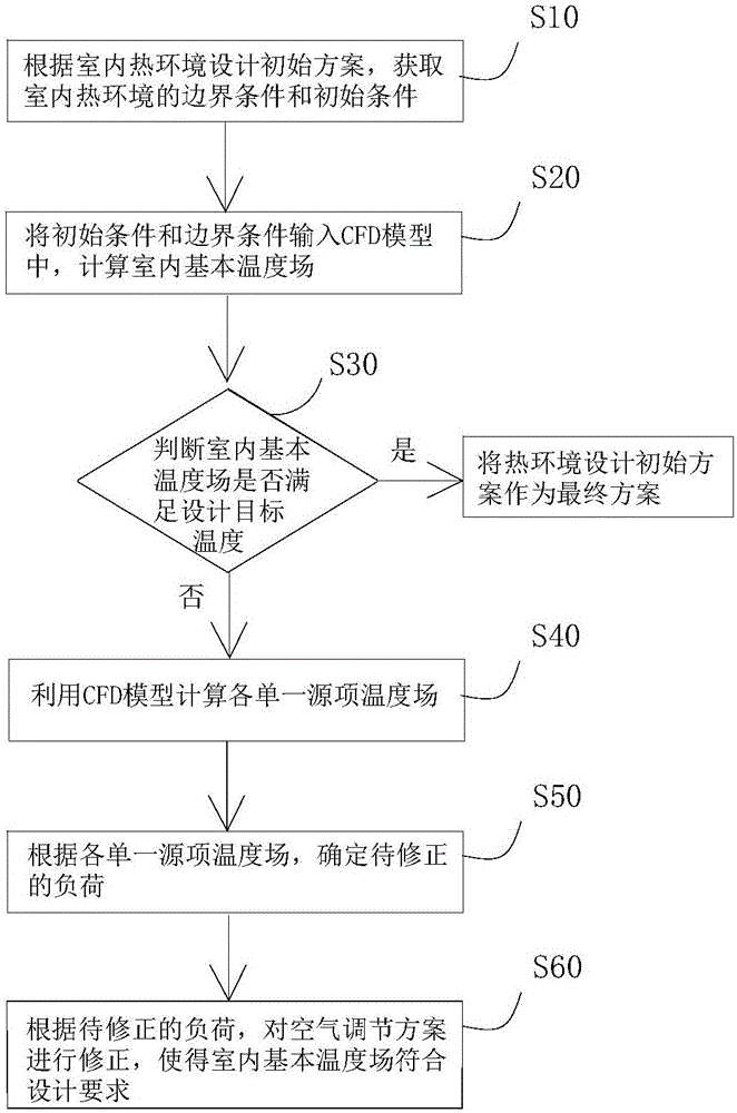
[0094] In the indoor thermal environment, the sub-area air-conditioning system is not divided.

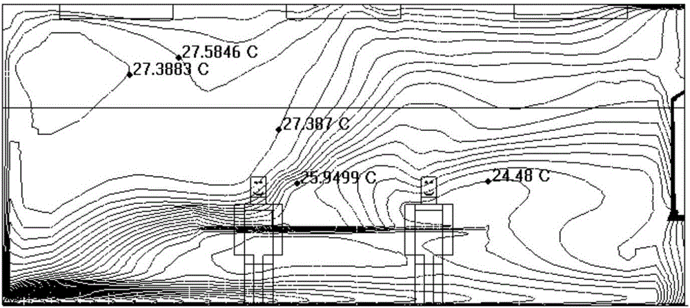
[0095] The indoor design target temperature is set at 26°C. According to the initial scheme of indoor thermal environment design, the initial conditions and boundary conditions are input into the CFD model, and the basic indoor temperature field is calculated. The results are as follows: figure 2 shown. from figure 2 It can be seen that in the basic temperature field formed by the initial scheme of indoor thermal environment design, the temperature in some areas is higher than the design target temperature, and the temperature in some areas is lower than the design target temperature. from figure 2 It can be seen that more heat generated by internal heat sources, lighting equipment, and enclosure structures flows to the upper right space of the room, while the lower left space of the room gets more cooling.

[0096] A single heat source or a single cold source is used as the...

Embodiment 2

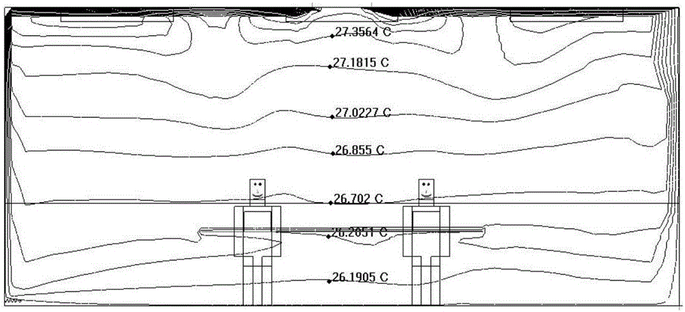
[0106] Set indoor thermal environment division and regional air-conditioning system, such as Figure 5 As shown, it is divided into two partitions, Partition 1 and Partition 2.

[0107] The indoor design target temperature is set at 26°C. According to the initial scheme of indoor thermal environment design, the initial conditions and boundary conditions are input into the CFD model, and the basic indoor temperature field is calculated. The results are as follows: Figure 5 shown. The sitting activity area is less than 1.3m, and the standing activity area is less than 2m. from Figure 5 For basic temperature field conditions, it is determined that the area for load correction (horizontal height 0.2m-1.3m) is located in Division 1.

[0108] In zoned air conditioning, an area is regarded as a thermal factor, all heat sources and cooling sources in this area are set with actual boundary conditions, and the entire area is a thermal factor. In turn, all the thermal factors in e...


PUM


Abstract

The invention discloses a method for analyzing an indoor thermal environment by utilizing a computational fluid dynamics (CFD) model. The method comprises a step S10 of obtaining boundary conditions and initial conditions of the indoor thermal environment according to an indoor thermal environment design initial scheme; a step S20 of calculating an indoor basic temperature field; a step S30 of judging whether the indoor basic temperature field meets a design objective temperature, and if the indoor basic temperature field meets the design objective temperature, taking the indoor thermal environment design initial scheme as a final scheme; if the indoor basic temperature field does not meet the design objective temperature, executing a step S40; the step S40 of utilizing the CFD model to calculate each single source item temperature field; a step S50 of determining a to-be-corrected load; and a step S60 of correcting an air conditioning scheme according to the to-be-corrected load, so that the indoor basic temperature field conforms to the design requirements. According to the method, by calculating temperature distribution under a single heat factor effect, heat needing to be corrected is determined quantitatively, an air conditioner load effectively meets the design requirements, and the conditions of a supercooling or superheating local area in practical application are avoided.

Description

technical field [0001] The invention relates to the technical field of indoor thermal environment of buildings, in particular to an analysis method of indoor thermal environment by using a CFD model. [0002] technical background [0003] With the increasing space of large buildings, the indoor thermal environment becomes more complex. The design of the air conditioning scheme not only needs to make the load meet the needs of the indoor thermal environment, but also needs to make each area meet the requirements of comfort, sanitation and energy consumption after actual operation. Require. At present, the commonly used design methods only use computational fluid dynamics (hereinafter referred to as: CFD) as a numerical analysis tool. The boundary conditions and initial conditions are obtained according to the load and design standards. Even, it is easy to have high density in some areas and low temperature in other areas. In addition, the pressure difference caused by the tem...

Claims


Application Information

Patent Timeline
IPC IPC(8): G06F17/50
CPCG06F30/367
Inventor 杨雨佳刘金祥张恺
Owner NANJING UNIV OF TECH
Why Eureka
Try Eureka