
State monitoring method and device for terminal equipment and terminal equipment

A technology of terminal equipment and status, which is applied in branch office equipment, telephone communication, electrical components, etc. It can solve the problems of mobile phone screen turning off and turning on, fluctuating, flickering screen, etc., and achieve the effect of avoiding flickering screen phenomenon

Active Publication Date: 2017-01-25
GUANGDONG OPPO MOBILE TELECOMM CORP LTD
View PDF9 Cites 22 Cited by
  • Summary
  • Abstract
  • Description
  • Claims
  • Application Information

AI Technical Summary

Problems solved by technology

However, when the user keeps flipping the phone up and down under strong sunlight, the infrared light intensity value obtained by the receiving end of the proximity sensor fluctuates constantly, causing the phone to turn off the screen and turn on the screen continuously, resulting in a flickering phenomenon.

Method used


Image

  • State monitoring method and device for terminal equipment and terminal equipment
  • State monitoring method and device for terminal equipment and terminal equipment
  • State monitoring method and device for terminal equipment and terminal equipment

Examples


example 1

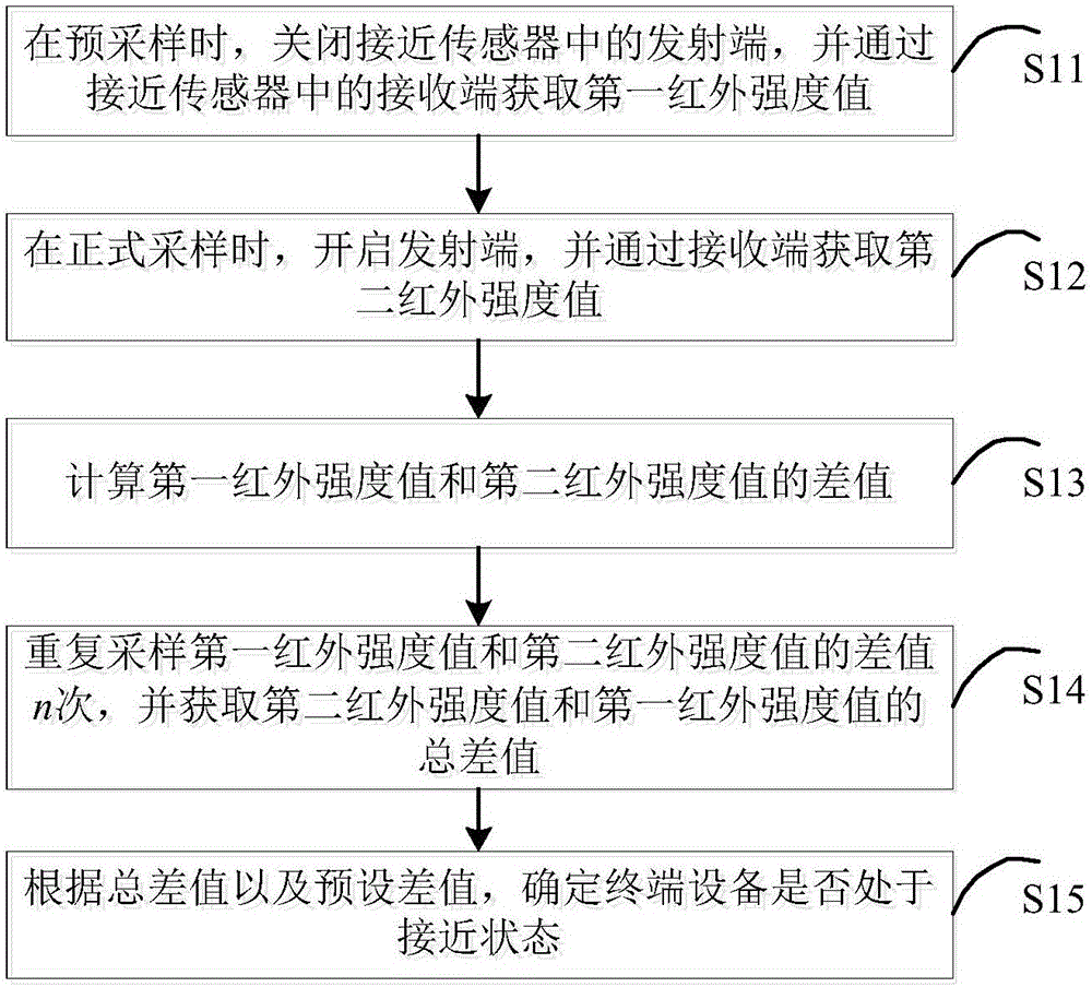
[0108] Example 1: The preset difference includes: a first threshold and a second threshold, and the first threshold is greater than the second threshold.

[0109] Specifically, after the normal light sampling mode of the proximity sensor is turned on, the transmitter is turned on, and the third infrared intensity value is read from the receiver. Comparing the third infrared intensity value with the first threshold and the second threshold, if the third infrared intensity value is greater than the first threshold, it is determined that the terminal device is in an approaching state; if the third infrared intensity value is less than the second threshold, then it is determined that the terminal device is away.

example 2

[0110] Example 2: The preset difference includes: a preset threshold.

[0111] Specifically, after the normal light sampling mode of the proximity sensor is turned on, the transmitter is turned on, and the third infrared intensity value is read from the receiver. If the third infrared intensity value is greater than the preset threshold, it is determined that the terminal device is in an approaching state; if the third infrared intensity value is smaller than the preset threshold, it is determined that the terminal device is in a far away state.

[0112] The state monitoring method of the terminal equipment in the embodiment of the present invention, by detecting whether the light intensity value of the environment where the terminal equipment is located is greater than the preset threshold value, when the light intensity value is greater than the preset threshold value, the proximity sensor is controlled to enter the strong light sampling mode. When the intensity value is les...


PUM


Abstract

The invention discloses a state monitoring method and device for terminal equipment and the terminal equipment. The method comprises the following steps: during pre-sampling, switching off a transmitting end in a proximity transducer, and reading a first infrared intensity value through a receiving end in the proximity transducer; during formal sampling, starting the transmitting end, and reading a second infrared intensity value from the receiving end; calculating a difference value between the second infrared intensity value and the first infrared intensity value; repeatedly sampling to obtain n difference values, and acquiring a total difference value between the second infrared intensity value and the first infrared intensity value; determining whether the terminal equipment is in a proximity state or not according to the total difference value and a preset difference value. Through the method, internal infrared rays and external interference infrared rays can be identified intelligently, and the phenomenon of splash screen caused by continuous change of the illumination intensity of the mobile terminal by a user in a strong light environment is avoided.

Description

technical field [0001] The present invention relates to the technical field of mobile terminals, in particular to a state monitoring method and device for terminal equipment and terminal equipment. Background technique [0002] Usually, when the mobile phone is close to the face in the process of making and receiving a call, the screen is turned off to prevent false triggering. This method is mainly realized by a proximity sensor, wherein the proximity sensor includes two parts, a transmitting end, which emits infrared light, and a receiving end, which receives infrared light. When an object approaches the proximity sensor, it reflects infrared light. The internal chip processor of the receiving end of the proximity sensor includes an analog-to-digital converter, which can obtain the specific infrared light intensity value when the object approaches. When there is no object occlusion, the intensity value at the receiving end is the smallest; as the object approaches, the i...

Claims


Application Information

Patent Timeline
IPC IPC(8): H04M1/725
CPCH04M1/72403
Inventor 周意保
Owner GUANGDONG OPPO MOBILE TELECOMM CORP LTD
Features
  • Generate Ideas
  • Intellectual Property
  • Life Sciences
  • Materials
  • Tech Scout
  • Unparalleled Data Quality
  • Higher Quality Content
  • 60% Fewer Hallucinations
Learn More