
Rotary table apparatus and electric discharge machine having the same

A rotary table and cable technology, which is applied to electric processing equipment, metal processing machine parts, accessory devices, etc., and can solve the problems of low assembly efficiency, cable damage, and poor operability of the rotary table device 1

Active Publication Date: 2017-02-01
FANUC LTD
View PDF10 Cites 0 Cited by
  • Summary
  • Abstract
  • Description
  • Claims
  • Application Information

AI Technical Summary

Problems solved by technology

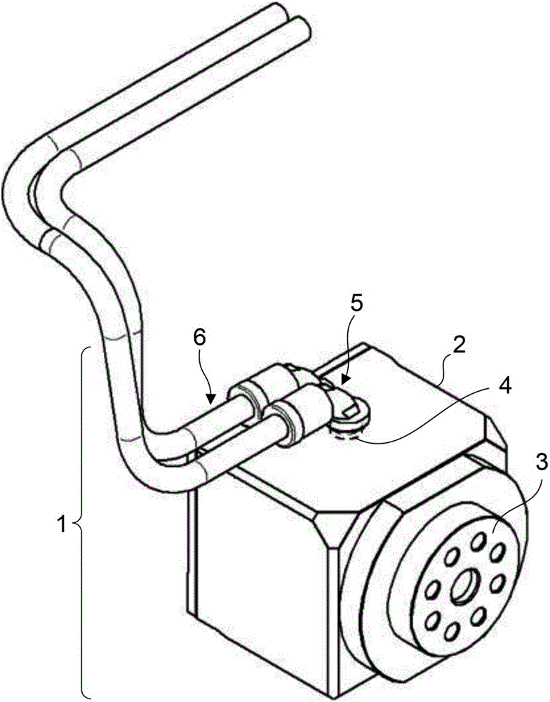
However, for the operation of the joint 5, special tools are often required, and the wrong fixing method will lead to poor waterproof performance of the joint 5. Therefore, it is not recommended to be performed by ordinary workers.
[0005] In addition, in the figure 1 In the method of directly attaching the connector 5 to the turntable main body 2, there is a problem that the cable insertion hole 4 cannot be made larger than the size of the connector 5 in terms of the structure of the connector 5.
That is, when the connector installed at the terminal of a cable (not shown) for motor driving or the like is larger than the cable insertion hole 4, the cable cannot pass through the cable insertion hole 4, so it is necessary to pass the cable only through the cable insertion hole 4 After that, the connector is installed at the end of the cable, so the assembly efficiency of the turntable device 1 is low
[0006] Although this problem can be solved by enlarging the joint 5, the free pipe 6 is also enlarged in proportion to the joint 5, so that the cost of the parts increases
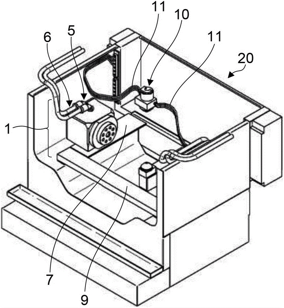
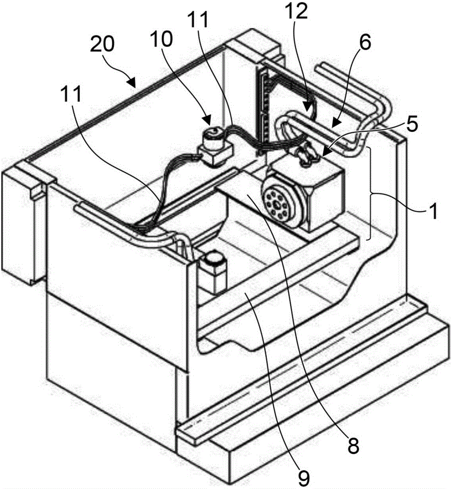
In addition, when the free tube 6 is extremely large with respect to the diameter of the cable passing through the free tube 6, not only the cable will be rubbed and damaged in the free tube 6, but also when the turntable device 1 is fixed to the processing tank 20, the free tube 6 will be damaged. In the case of the inner table, since the free pipe 6 is thick, the operability is deteriorated, and it is difficult to fix along the processing groove 20

Method used


Image

  • Rotary table apparatus and electric discharge machine having the same
  • Rotary table apparatus and electric discharge machine having the same
  • Rotary table apparatus and electric discharge machine having the same

Examples


Embodiment Construction

[0019] Hereinafter, embodiments of the present invention will be described along with the drawings.

[0020] Figure 4 It is a block diagram of a turntable device using an adapter. The structure of the turntable device 1 is based on the turntable main body 2, and a bearing (not shown) is installed inside, and the panel 3 installed on the inner ring of the bearing (not shown) can be arbitrarily positioned relative to the turntable main body 2. rotate. Such as Figure 4 As shown, an adapter 13 is arranged directly above the cable insertion hole 4 of the turntable main body 2 . A cable insertion hole 14 is also formed in the adapter 13 . The adapter 13 is a cover-shaped member, and a plurality of bolt mounting holes (screw holes) are provided in the peripheral portion. Bolt holes are provided in the turntable main body 2 . Therefore, the adapter 13 can be fixed to the turntable main body 2 using bolts, or can be fixed by a combination of bolts and lock nuts, or the like.

...


PUM


Abstract

A rotary table apparatus includes: a rotary table casing; a face plate which is pivotally supported by the rotary table main body and can be freely rotated;a connector which is inserted into a cable which enable the face plate to rotate; and a free tube. An adaptor is mounted between the rotary table main body and the connector; and the adpater can be changed relative to the installation direction of the rotary table main body and can be freely mounted and dismounted.

Description

technical field [0001] The present invention relates to a turntable device and an electric discharge machine provided with the turntable device. Background technique [0002] Such as figure 1 As shown, the structure of the turntable device 1 is based on the turntable main body 2, and a bearing (not shown) is installed inside, and the panel 3 installed on the inner ring of the bearing (not shown) is opposite to the turntable main body 2 Can be rotated arbitrarily. In addition, a cable insertion hole 4 for driving a motor or the like is opened in the upper surface (or side surface) of the turntable main body 2 . Just above it, a connector 5 is attached so as to close the cable insertion hole 4 . A free pipe 6 is inserted into the joint 5, and a cable (not shown) for driving a motor or the like passes through the joint 5 and the free pipe 6, so that the watertightness of the turntable device 1 can be removed from the turntable device 1 while maintaining the waterproofness of...

Claims


Application Information

Patent Timeline
Patent Type & Authority Applications(China)
IPC IPC(8): B23H7/02B23H11/00
CPCB23H7/02B23H11/00B23H11/003B23Q1/0009B23Q1/52B23H1/00B23Q1/00
Inventor 山崎瑞穗
Owner FANUC LTD
Learn More