
Water-stop structure and construction method at the expansion joints of urban underground comprehensive pipe gallery

A technology for integrated pipe gallery and expansion joints, applied in underwater structures, infrastructure engineering, water conservancy projects, etc., can solve problems such as pipelines, pipeline safety hazards, water curtain holes, misalignment, etc., to achieve low investment costs and avoid construction schedules Long, fast construction effect

Active Publication Date: 2018-10-30
CHINA 22MCC GROUP CORP
View PDF6 Cites 0 Cited by
  • Summary
  • Abstract
  • Description
  • Claims
  • Application Information

AI Technical Summary

Problems solved by technology

However, in many places where the groundwater level is high, especially in the coastal areas with complex geological conditions of sediment and silt, even if rubber waterstops (or steel waterstops) are installed at the expansion joints of the concrete pipe gallery, with the underground Due to the comprehensive influence of various factors such as the creeping of the silt, the dynamic load of a large number of vehicles on the ground, the lateral pressure generated by the surrounding buildings, and the uneven settlement of the structure, the expansion joints of the pipe gallery will cause different degrees of dislocation, floating, and cracking of the waterstop, etc. phenomenon, leading to water leakage in the expansion joints of the pipe gallery, and the phenomenon of "water curtain hole" in severe cases, which brings safety hazards to various pipes and pipelines in the pipe gallery

Method used


Image

  • Water-stop structure and construction method at the expansion joints of urban underground comprehensive pipe gallery
  • Water-stop structure and construction method at the expansion joints of urban underground comprehensive pipe gallery
  • Water-stop structure and construction method at the expansion joints of urban underground comprehensive pipe gallery

Examples


Embodiment Construction

[0022] The present invention will be described in detail below in conjunction with the accompanying drawings and embodiments, but the present embodiments do not constitute any limitation to the present invention.

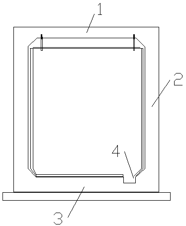
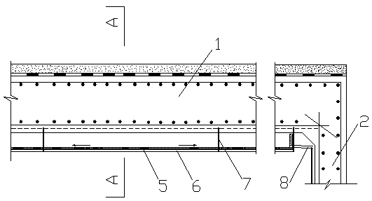
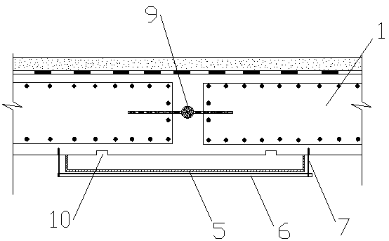
[0023] see figure 1 , figure 2 , image 3 , a water-stop structure at the expansion joints of the urban underground comprehensive pipe gallery, rubber waterstops 9 are arranged at the expansion joints of the pipe gallery, and drainage ditches 4 are provided on one side of the concrete bottom plate 3 of the pipe gallery; the concrete roof 1 of the pipe gallery corresponds to The expansion joint passes through the bracket 6 and the expansion screw 7 to hoist the sump 5, and the two sides of the roof expansion joint are respectively provided with grooves, the grooves form a drip line 10, and the seepage water on the top plate drips from the drip line 10 and collects in the sump 5 ; Concrete walls 2 on both sides of the pipe corridor are respectively provided with le...


PUM


Abstract

The invention relates to a water stop structure arranged at the position of an expansion joint of an urban underground comprehensive pipe rack and a construction method of the water stop structure. The water stop structure comprises a rubber water stop belt and a drainage ditch. The rubber water stop belt is arranged at the position of the expansion joint of the pipe rack, and the drainage ditch is formed in one side of a pipe rack bottom plate in a pass length manner. The position, corresponding to the expansion joint, of a concrete top plate of the pipe rack is provided with a catch basin. The positions, corresponding to the expansion joint, of concrete walls on the two sides of the pipe rack are provided with leakage water diversion trenches correspondingly. V-shaped expansion joint buckle covers are arranged on the outer sides of the leakage water diversion trenches, a flow guiding pipe is arranged between each of the two ends of the catch basin and the corresponding leakage water diversion trench, water outlets are formed in the bottoms of the leakage water diversion trenches, and leakage water is drained into the drainage ditch through the water outlets via a pipe rack bottom plate structure. According to the water stop structure and the construction method of the water stop structure, a traditional blockage method is avoided while a guiding method is used for achieving the purpose of water stop, local materials are used, the construction method is simple and practicable, and the construction speed is high; meanwhile, the input cost is low, the effect is obvious, and a series of defects that the construction period is long, the task is heavy, cost is high, and repeated maintaining is needed are overcome, wherein the defects are caused by traditionally adopting the blockage as the main construction method.

Description

technical field [0001] The invention relates to a construction technology for waterproofing and leakage of urban underground comprehensive pipe gallery, in particular to a water-stop structure at expansion joints of urban underground comprehensive pipe gallery and a construction method thereof. Background technique [0002] The underground integrated pipe gallery refers to the selective placement of various pipelines and auxiliary equipment such as water supply, drainage, electricity, telecommunications, optical cables, heat, gas, etc., in a larger pipe gallery (or pipe trench). The state has defined the utility tunnel as an important measure to innovate urban infrastructure construction. The people's livelihood project supported by the state aims to solve the long-standing problems of backward urban underground infrastructure. The comprehensive pipe gallery has the outstanding advantages of strong carrying capacity, high service level, saving urban land resources, advocatin...

Claims


Application Information

Patent Timeline
Patent Type & Authority Patents(China)
IPC IPC(8): E02D29/045E02D29/16
CPCE02D29/04E02D29/16
Inventor 王代发
Owner CHINA 22MCC GROUP CORP
Learn More