
Grouting pipe connecting structure at ground crack

A technology for grouting pipes and ground fissures, which is applied to underground chambers, underwater structures, and infrastructure engineering, etc. It can solve the problems of easy blockage of holes, troubles for construction teams, and non-reusability, etc. Filling effect, fast installation effect

Pending Publication Date: 2021-02-19
CHINA CONSTR FIRST BUILDING GRP CORP LTD
View PDF3 Cites 0 Cited by
  • Summary
  • Abstract
  • Description
  • Claims
  • Application Information

AI Technical Summary

Problems solved by technology

These defects are the fatal wound in the concrete pouring project, which directly affects the quality and service life of the concrete pouring project. This problem has become a difficult problem in the concrete pouring construction, and it has plagued the construction team for a long time.
[0003] At present, to deal with the problem of cracks, waterstops, water-swelling waterstops, waterstop glue, post-drilling and high-pressure grouting are mostly used to seal the cracks. The main problems are as follows: (1) The process is complicated, time-consuming and laborious, and the sealing effect is low. Not good, such as prior art CN105696804A A kind of convenient filling device and construction method for cracks in building walls, including telescopic arm, connected to the suction cup below the telescopic arm, and the fine-tuning turntable is installed on the arm frame to drive the telescopic arm to move relative to the suction cup. 360-degree rotation; one end of the telescopic arm is equipped with a nozzle, and the other end is installed with an elastic driven disk flush with the suction cup; the top of the nozzle is connected with a grouting pipe and an air injection pipe, and the switch is installed on the nozzle. Side; the nozzle is a telescopic nozzle with a semicircular protective cover installed on one side, and the flattening roller is installed on the opposite side of the semicircular protective cover; the nozzle is controlled by a single-chip microcomputer, and a grayscale sensor is installed on it ; Its structure is complex, time-consuming and labor-intensive to install and use
(2) A single time can only be used for the repair of one gap or the repair of multiple fixed-distance gaps. CN106320729A is a water-stopping structure of a pre-embedded grouting pipe supplemented with water-expandable water-stop strips, which includes pre-embedded grouting Conduit, grouting main pipe and water-swelling water-stop strip fixed by connectors and structures, the grouting main pipe is provided with grouting holes every 20cm to 30cm, and the grouting holes are wrapped by a single-layer filter , the grouting hole is temporarily blocked with adhesive tape; it uses the grouting hole for grouting, the hole is easy to block, and can only be used for fixed distance grouting; (3) it cannot be reused, and when the amount of repairing materials cannot be estimated , easily cause waste of materials, such as prior art CN207032923U a kind of concrete crack repair device, comprising a grouting device, the grouting device comprises a grouting tube, the upper opening of the grouting tube is provided with a gland, and the lower end of the grouting tube is provided with A hollow grout head connected to the inner cavity of the grouting cylinder; a through hole is provided in the center of the gland, and a hollow pressure rod is installed sliding in the through hole, and the lower end of the hollow pressure rod is located in the inner cavity of the grouting cylinder A hollow piston body matching the inner wall of the grouting cylinder is installed; the lower end surface of the piston body is provided with an arc-shaped installation cavity connected with the center hole of the piston body, and an arc-shaped installation cavity matching the arc-shaped installation cavity is installed in the arc-shaped installation cavity. The center hole of the piston body is equipped with a hollow support plate, the hollow support plate is provided with a center hole of the support plate, the upper end of the arc-shaped plug is provided with a connecting rod, and the connecting rod slides through the center hole of the support plate. The upper end of the connecting rod is screwed with a lock nut, and a support spring is set on the connecting rod between the lock nut and the upper end surface of the hollow support plate; it can only be used for grouting once and cannot be reused

Method used


Image

  • Grouting pipe connecting structure at ground crack
  • Grouting pipe connecting structure at ground crack

Examples


Embodiment Construction

[0019] The specific implementation manners according to the present invention will be described below in conjunction with the accompanying drawings.

[0020] In the following description, many specific details are set forth in order to fully understand the present invention, but the present invention can also be implemented in other ways different from those described here, therefore, the present invention is not limited to the specific embodiments disclosed below limit.

[0021] In order to solve the problems of complex procedures, time-consuming and labor-intensive traditional construction methods, inability to be flexibly used in multiple cracks, and poor plugging effect, the invention provides a connection structure for grouting pipes at ground fissures.

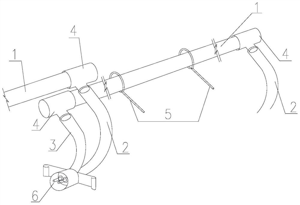
[0022] Such as figure 1 As shown, the grouting pipe connection structure at the ground fissure includes at least two grouting pipe structural units, wherein a single grouting pipe structural unit includes: grouting pipe...


PUM


Abstract

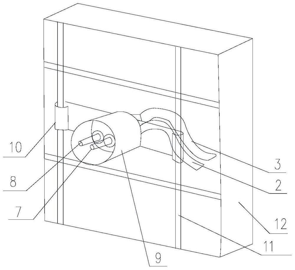
The invention provides a grouting pipe connecting structure at a ground crack. The grouting pipe connecting structure at the ground crack comprises at least two grouting pipe structure units, and eachgrouting pipe structure unit comprises grouting pipes, grouting guide pipes, grout outlet guide pipes, connecting pipes, not less than two auxiliary fixing steel bars and a grouting box. The groutingpipes are full-section grouting pipes capable of being grouted repeatedly, the number of the grouting pipes is not less than 2, the grouting guide pipes and the grout outlet guide pipes connected with the grouting pipes are correspondingly arranged at the two ends of each grouting pipe, and the not less than two auxiliary fixing steel bars are arranged on a pipe body of each grouting pipe. The grouting guide pipes are connected with the grouting pipes through the connecting pipes, the grout outlet guide pipes are connected with the grouting pipes through the connecting pipes, and the adjacentgrouting guide pipes and the grout outlet guide pipes are correspondingly connected with the grouting box. The grouting pipe connecting structure is rapid to install, simple in construction process and capable of achieving repeated grouting.

Description

technical field [0001] The invention relates to the field of building construction, in particular to a connection structure for grouting pipes at ground fissures. Background technique [0002] During the construction process, when tunnels, subways, basements and other large urban underground spaces pass through the ground fissure area, due to the small co-deformation ability of deformation joints and ground fissure movement in the ground fissure area, and the concrete pouring materials in different sections of the building The difference in settlement, as well as the difference in thermal expansion and contraction coefficients between the poured solidified concrete and the cast-in-place concrete, further lead to the generation of cracks. These defects are fatal to the concrete pouring project, which directly affects the quality and service life of the concrete pouring project. This problem has become a difficult problem in the concrete pouring construction, and it has long p...

Claims


Application Information

Patent Timeline
Patent Type & Authority Applications(China)
IPC IPC(8): E02D29/16E02D15/02E21D11/10
CPCE02D15/02E02D29/16E21D11/10
Inventor 李诗浩梁存君贾鑫鑫崔仲卉张川金青
Owner CHINA CONSTR FIRST BUILDING GRP CORP LTD
Learn More