Eureka AIR delivers breakthrough ideas for toughest innovation challenges, trusted by R&D personnel around the world.

Array turbulent flow column jet cooling device

A technology of jet cooling and cooling devices, which is applied in the direction of cooling/ventilation/heating transformation, electrical components, electrical equipment structural parts, etc., can solve the problems that cannot fully meet the heat dissipation requirements of large-scale integrated circuits, and achieve improved temperature uniformity Effect, the effect of improving the heat exchange capacity

Inactive Publication Date: 2020-01-07
BEIJING JIAOTONG UNIV
View PDF2 Cites 5 Cited by
  • Summary
  • Abstract
  • Description
  • Claims
  • Application Information

AI Technical Summary

Problems solved by technology

[0003] The traditional natural air convection has gradually been replaced by air forced convection and liquid convection cooling technology, but it still cannot fully meet the heat dissipation requirements of large-scale integrated circuits

Method used


Image

  • Array turbulent flow column jet cooling device
  • Array turbulent flow column jet cooling device
  • Array turbulent flow column jet cooling device

Examples


Embodiment Construction

[0019] In order to illustrate the present invention more clearly, the present invention will be further described below in conjunction with preferred embodiments and accompanying drawings. Similar parts in the figures are denoted by the same reference numerals. Those skilled in the art should understand that the content specifically described below is illustrative rather than restrictive, and should not limit the protection scope of the present invention.

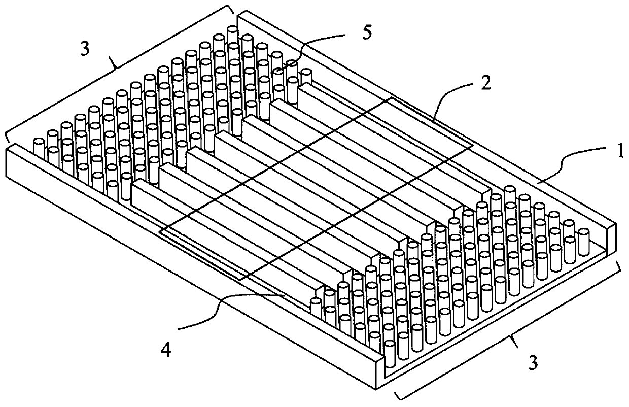
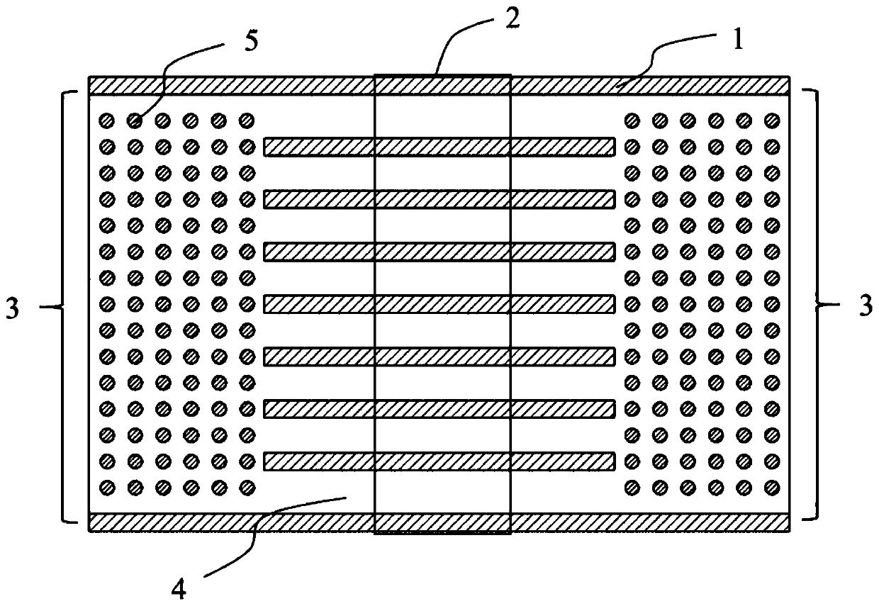
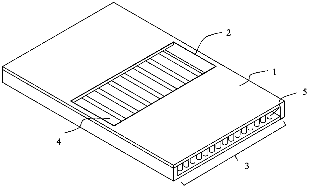
[0020] The invention provides an array spoiler jet cooling device, such as Figures 1 to 3 As shown, it includes: a housing 1, a cooling medium inlet 2 at the upper end of the housing 1, two outlets 3 symmetrically arranged at both ends of the housing 1 along the center, and symmetrically arranged in the first half of the inlet 2. There are multiple columns of rectangular channels 4 with the same channel spacing, and the spoiler column array 5 is arranged symmetrically along the center in the second half.

[0021] In the ...


PUM


Abstract

The invention discloses an array turbulent flow column jet cooling device, and belongs to the technical field of radiators. The cooling device is provided with a housing, a cooling working medium inlet, a cooling working medium outlet and a turbulent flow column array. The front half section of the cooling device is multiple columns of rectangular channels at equal intervals, and the rear half section of the cooling device is a turbulent flow column array which is symmetrically arranged along the center. Through the jet impingement cooling technology, gas or liquid is directly jetted to a cooled or heated surface through a rectangular nozzle (inlet) under the action of pressure difference, so that the flow path is short and a flow boundary layer on the impacted surface is thin, and an areadirectly impacted generates a very strong heat exchange effect; and the turbulent flow column array is arranged on the rear half section of the cooling device, so that the heat exchange area of the device and fluid is increased, the flow boundary layer formed in the flow channels is damaged, disturbance in flowing is increased, and furthermore, the heat exchange enhancing effect is further achieved, and the temperature equalizing effect of the cooling device is greatly improved.

Description

technical field [0001] The invention belongs to the field of heat dissipation devices and relates to a jet impingement cooling device. Background technique [0002] With the advancement of microelectronics technology, the development of miniaturization and miniaturization of electronic devices has been promoted. The reduction in the size of electronic devices has also greatly increased the heat flux of electronic devices, which puts forward more stringent requirements for the heat dissipation of microelectronic devices. Therefore, effectively solving the heat dissipation problem of high heat flux has become a key technology that must be solved in the development of electronic equipment. [0003] The traditional natural air convection has gradually been replaced by air forced convection and liquid convection cooling technology, but it is still unable to fully meet the heat dissipation requirements of large-scale integrated circuits. As a typical means of enhancing heat trans...

Claims


Application Information

Patent Timeline
Patent Type & Authority Applications(China)
IPC IPC(8): H05K7/20
CPCH05K7/20272
Inventor 马浩段志鹏苏良彬
Owner BEIJING JIAOTONG UNIV
Why Eureka
Eureka Blog
Learn More