Bidirectional TMD control device and parameter determination method

A control device, vertical technology, applied in the direction of building components, building structure, building type, etc., can solve the problem of not considering the damping of the superstructure

Inactive Publication Date: 2017-02-01
LANZHOU UNIVERSITY OF TECHNOLOGY
View PDF11 Cites 17 Cited by
  • Summary
  • Abstract
  • Description
  • Claims
  • Application Information

AI Technical Summary

Problems solved by technology

[0005] None of the above researchers con

Method used


Image

  • Bidirectional TMD control device and parameter determination method
  • Bidirectional TMD control device and parameter determination method
  • Bidirectional TMD control device and parameter determination method

Examples


Embodiment Construction

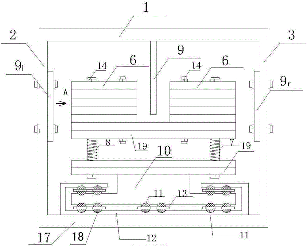
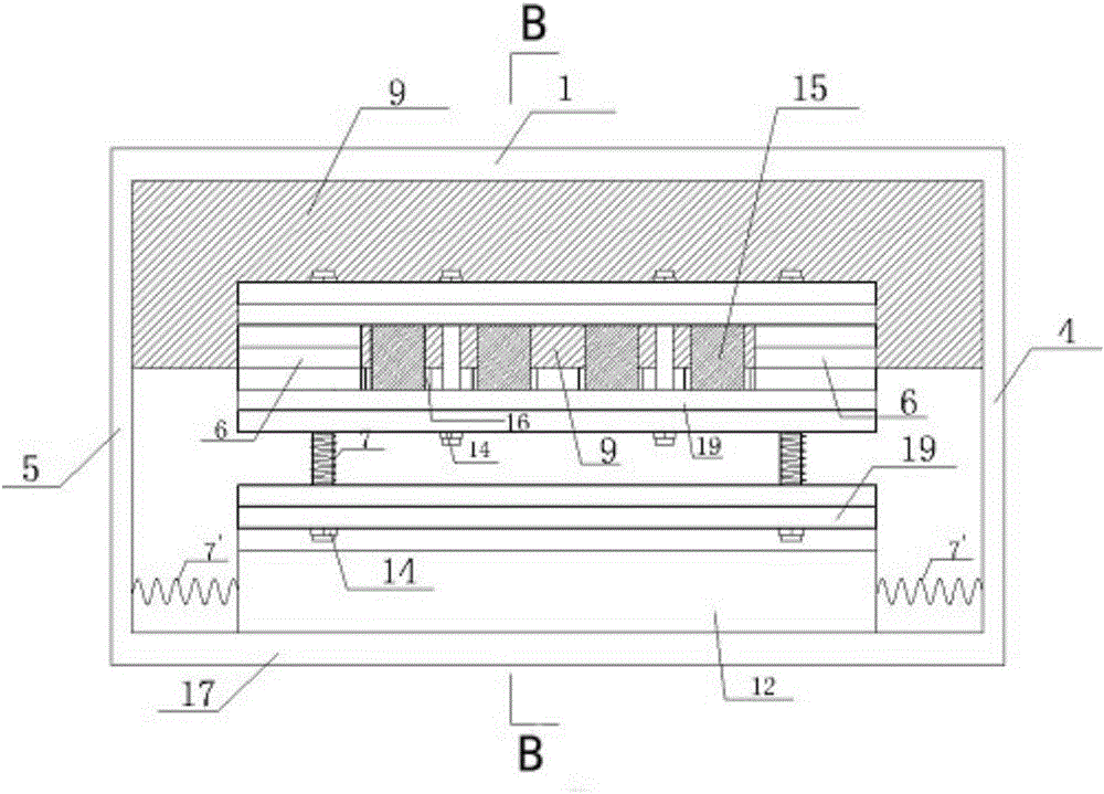
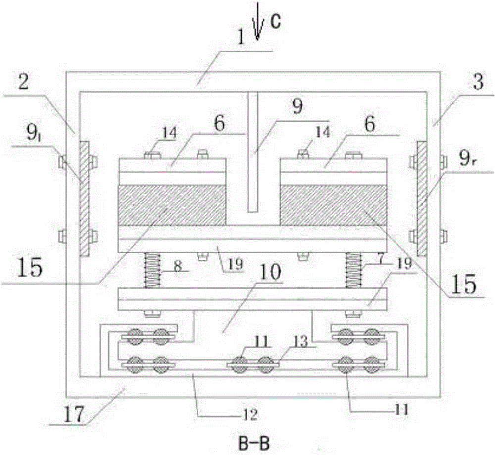
[0080] Such as figure 1 , figure 2 , image 3 , Figure 4 , Figure 5 , Figure 6 As shown, the two-way TMD control device has a base plate 17 placed horizontally, the second steel plate 2, the third steel plate 3, the fourth steel plate 4, and the fifth steel plate 5 are vertically installed on the base plate 17 respectively, and the first steel plate 1 is parallel to the base plate 17 , constituting a semi-sealed cube, the mass block 6 is installed on the sixth steel plate 19 through the guide rod 8, and the vertical spring 7 that can provide vertical stiffness and control the vertical movement of the TMD is nested on the guide rod 8, the first The six steel plates 19 are installed on the upper end of the T-shaped base 10, and the lower part of the base 10 is nested in the track groove 18 of the track assembly 12 through the steel ball 11 and the steel ball slot 13; the upper end of the copper plate 9 is installed on the first steel plate 1 At the middle position, the ...


PUM


Abstract

The invention discloses a bidirectional TMD control device and a parameter determination method. Four steel plates are vertically arranged on a bottom plate which is horizontally disposed, a first steel plate is parallel to the bottom plate, mass blocks (6) are installed on a steel plate (19) through guide rods, and the guide rods are sleeved with vertical springs. The lower portion of a base is embedded in a rail groove of a rail assembly (12) through steel balls and steel ball clamping slots; a copper plate (9) is installed at the middle portion of the first steel plate, a left copper plate (91) and a right copper plate (9r) are installed on the portions, corresponding to the mass blocks, of the second steel plate and the third steel plate respectively, permanent magnets are installed in clamping slots, and the two ends of transversal springs (7') are connected with the fourth steel plate and the base respectively; the two ends of another pair of transversal springs (7') are connected with the fifth steel plate (5) and the base (10) respectively. The parameter determination method comprises the following steps: optimizing the TMD vertical parameter and the TMD horizontal parameter which are obtained by calculation in finite element software to obtain an optimal solution; then determining the final parameter of a TMD.

Description

technical field [0001] The invention relates to civil engineering technology, in particular to vibration reduction control technology. Background technique [0002] With the development of civil engineering, high-strength materials have been widely used in buildings and bridges, and large-span floors and stairs are also increasing. Buildings and bridges made of this material are lighter in weight. The span is larger and the natural frequency is smaller, which is closer to the walking frequency of pedestrians. This will easily cause structural resonance and produce a larger response. In severe cases, the vibration will cause buildings, bridges and other buildings (structures) to collapse and damage. In order to reduce the occurrence of accidents and the loss of life and property, the vibration control of such long-span structures is usually carried out passively, that is, to increase the structural damping, energy-absorbing vibration-reducing devices are required. [0003] ...

Claims


Application Information

Patent Timeline
IPC IPC(8): E04H9/02E04B1/98
CPCE04H9/021E04H9/0215
Inventor 朱前坤蒲兴龙惠晓丽南娜娜张琼杜永峰
Owner LANZHOU UNIVERSITY OF TECHNOLOGY
Why Eureka
Try Eureka