A super high pressure axial piston pump

An axial plunger pump, ultra-high pressure technology, applied in the direction of pumps, pump components, multi-cylinder pumps, etc., can solve the problems of damaging the service life, hindering the pressure of the plunger pump, etc., to increase the working range, increase the power-to-weight ratio, Overall compact structure

Active Publication Date: 2019-05-10
BEIJING HUADE HYDRAULIC INDAL GROUP
View PDF7 Cites 1 Cited by
  • Summary
  • Abstract
  • Description
  • Claims
  • Application Information

AI Technical Summary

Problems solved by technology

[0003] At present, the axial plunger pump / motor is hindered from increasing the pressure of the plunger pump due to structural, material and other reasons during actual work, and long-term high pressure will also damage its service life

Method used


Image

  • A super high pressure axial piston pump
  • A super high pressure axial piston pump
  • A super high pressure axial piston pump

Examples


Embodiment Construction

[0030] In order to further explain the technical means and effects of the present invention to achieve the intended purpose of the invention, the specific implementation and features of an ultra-high pressure axial piston pump proposed according to the present invention will be described below in conjunction with the accompanying drawings and preferred embodiments. And its effect, detailed description is as follows.

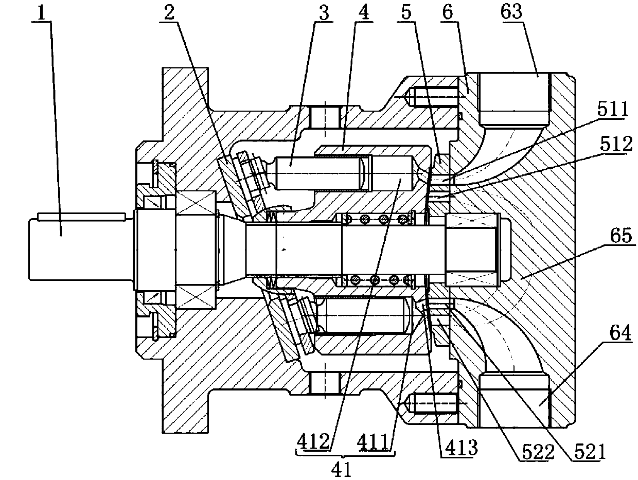
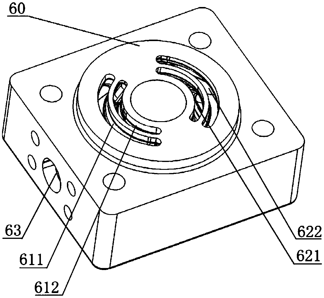
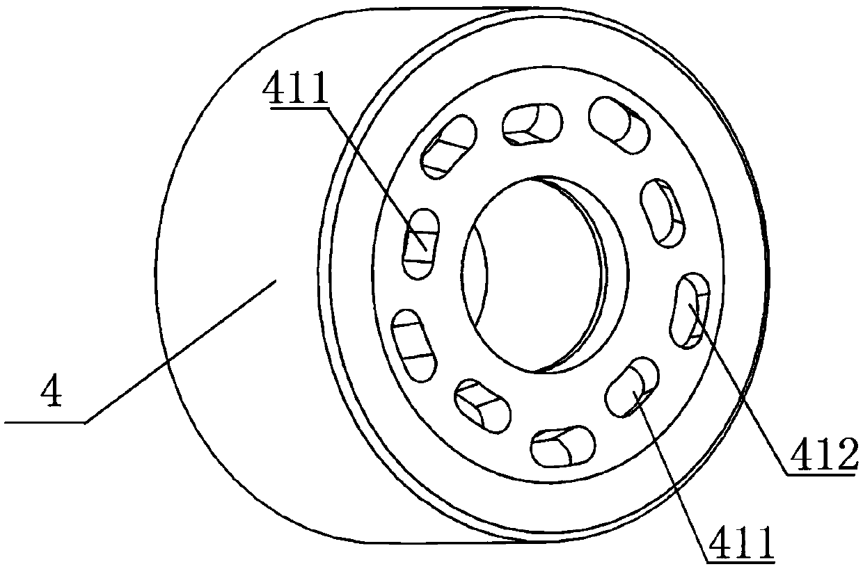
[0031] see Figure 1 to Figure 3 , The present invention discloses an ultra-high pressure axial piston pump, comprising a transmission shaft 1, a swash plate 2, a plunger 3, a cylinder body 4, a flow distribution plate 5, and a rear cover 6.

[0032] The swash plate 2 is sheathed on the transmission shaft 1 . One end of the plunger 3 is installed on the swash plate 2 . There is an inclination angle between the swash plate 2 and the transmission shaft axis. An oil inlet side and an oil outlet side are formed on both sides of the drive shaft axis. Such as figu...


PUM


Abstract

The invention discloses a ultrahigh-pressure axial plunger pump. The ultrahigh-pressure axial plunger pump comprises a transmission shaft, an inclined disc and a plunger; the inclined disc coats the transmission shaft; one end of the plunger is mounted on the inclined disc; and a dip angle is formed between the inclined disc and the axis of the transmission shaft. The ultrahigh-pressure axial plunger pump further comprises a cylinder body provided with multiple cylinder body holes uniformly staggered around the axis of the cylinder body; the other end of the plunger is mounted in the cylinder body holes; the cylinder body, a distribution disc and a back cover are tightly bonded in sequence; the cylinder body and the distribution disc coat the transmission shaft; the distribution disc and the back cover are provided with inner oil holes and outer oil holes alternately distributed; the cylinder body holes and the inner oil holes are communicated to form internal oil ways; the cylinder body holes and the outer oil holes are communicated to form external oil ways; one end of the transmission shaft is used for connecting with a driving device; and the other end of the transmission shaft is mounted at the front part of the internal oil way in the back cover. The ultrahigh-pressure axial plunger pump changes the fluid output pressure, and improves one time of the pressure grade to achieve the super pressure purpose.

Description

technical field [0001] The invention relates to an axial plunger pump, in particular to an ultra-high pressure hydraulic axial plunger pump. Background technique [0002] The hydraulic axial piston pump / motor is mainly composed of a transmission shaft, a housing, a swash plate, a plunger, a cylinder block, a spring, a bearing, a flow distribution plate, and a rear cover. The plungers are evenly distributed in the cylinder body along the circumference, there is an inclination angle γ between the swash plate and the axis of the cylinder body, the plunger is tightly pressed on the swash plate, the distribution plate is fixed and does not rotate, and the transmission shaft runs through the swash plate and the cylinder body with bearings at both ends Supported on the housing, the cylinder is connected to the drive shaft through splines. When the prime mover drives the cylinder body to rotate through the transmission shaft, the plunger is forced to reciprocate in the cylinder bod...

Claims


Application Information

Patent Timeline
Patent Type & Authority Patents(China)
IPC IPC(8): F04B1/12F04B53/16F04B53/00
CPCF04B1/12F04B1/122F04B53/162
Inventor 杨广文周宇焦玲李跃军杨华勇张晋姜继海
Owner BEIJING HUADE HYDRAULIC INDAL GROUP
Why Eureka
Try Eureka