Antenna mounting hole sealing plug used for electric power system

A technology for power systems and mounting holes, which is applied in the field of sealing plugs for antenna mounting holes in power systems, can solve the problems of elastic plugs coming out, the sealing performance of elastic plugs and mounting holes, and poor fixation, and achieve the effect of increasing sealing

Inactive Publication Date: 2017-02-01
国网山东省电力公司招远市供电公司
View PDF6 Cites 0 Cited by
  • Summary
  • Abstract
  • Description
  • Claims
  • Application Information

AI Technical Summary

Problems solved by technology

[0004] However, the above scheme has the following problems: 1. The antenna plug is an elastic plug, which is directly inserted into the mounting hole and sealed by tight extrusion between the antenna plug and the mounting hole. However, due to problems such as antenna swing and elastic plug aging, the The tightness between the elastic plug and the mounting hole gradually decreases, and in severe cases, the elastic plug may even come out; 2. The antenna plug lacks a support and protection structure for the antenna. Since the antenna has a certain length, it is easy to be exposed to wind under the action of the wind. Bending occurs; 3. The antenna plug is fixed by friction force, and the fixing force is poor, so the antenna plug and the antenna are easy to be stolen

Method used


Image

  • Antenna mounting hole sealing plug used for electric power system
  • Antenna mounting hole sealing plug used for electric power system
  • Antenna mounting hole sealing plug used for electric power system

Examples


Embodiment Construction

[0032] The present invention is described in further detail now in conjunction with accompanying drawing. These drawings are all simplified schematic diagrams, which only illustrate the basic structure of the present invention in a schematic manner, so they only show the configurations related to the present invention.

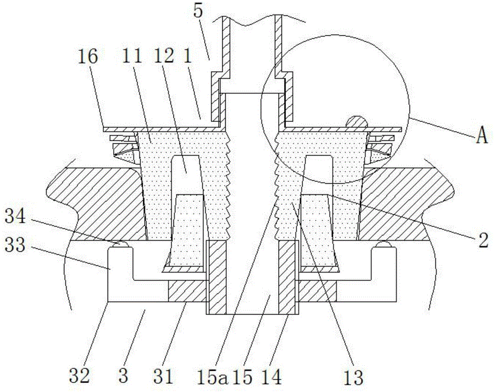
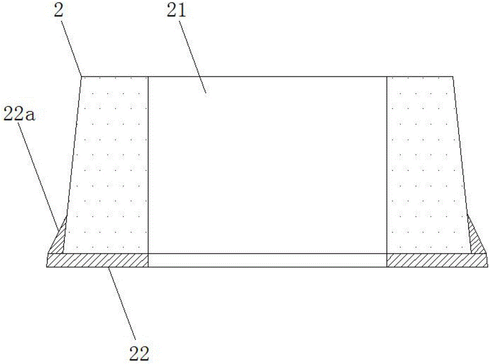
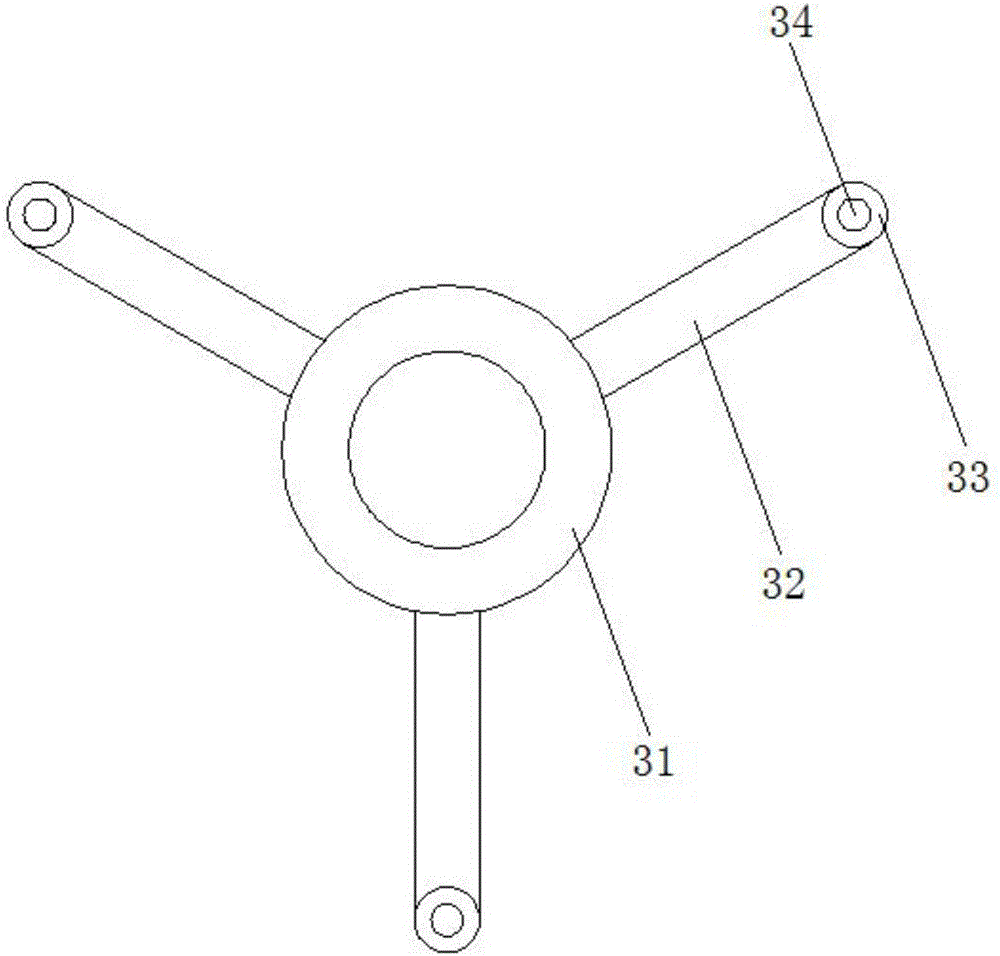
[0033] A sealing plug for an antenna installation hole in a power system, characterized in that it includes a plug body 1, a taper sleeve 2, a locking claw plate 3, a sealing kit, and a protective standpipe 5;

[0034] The plug body 1 includes a frustum-shaped outer plug 11 that is wide at the top and narrow at the bottom. The lower end of the outer plug 11 is recessed upward to form a circular groove 12. A frustum-shaped inner plug 13 that is wide at the top and narrow at the bottom. A screw 14 is glued to the lower end of the inner plug 13 . 1. The wire insertion channel 15 of the screw 14, the part of the wire insertion channel 15 located in the outer plug...


PUM


Abstract

The invention relates to an antenna mounting hole sealing plug used for an electric power system. The antenna mounting hole sealing plug comprises a plug body, a taper sleeve, a locking claw plate, a sealing sleeve member and a vertical protection tube. The plug body comprises an outer plug, a circular groove, an inner plug, a screw rod, a plug wire channel, a first annular plate, a first bulge loop, a screwed pipe and a stopping block. The taper sleeve is provided with an insertion hole, a second annular plate and a second bulge loop. The locking claw plate comprises a nut, a supporting claw, a rolling ball support and a rolling ball. The sealing sleeve member is arranged on the outer wall of the outer plug in a sleeving mode. The sealing sleeve member comprises a disc spring, an upper ring and a lower ring from top to bottom. The lower end face of the upper ring is gradually recessed upwards in an inward mode in the radial direction. The lower ring is a wedge-shaped ring with the inside being wide and the outside being narrow. The vertical protection tube at least comprises a wide tube body which is screwed to the screwed pipe and made of a hard material, and a slim tube body which is arranged on the wide tube body and made of an elastic material. According to the antenna mounting hole sealing plug, double-layer sealing is adopted, the sealing degree can be maintained regularly, supporting force can be given to an antenna so that the antenna can be prevented from being broken off, and the anti-theft effect is further achieved.

Description

technical field [0001] The invention relates to the technical field of sealing devices, in particular to a sealing plug for an antenna installation hole in a power system. Background technique [0002] During the operation of the power system, it is often encountered that the electronic instrument installed in the meter box needs to set up an antenna. At this time, it is necessary to open a mounting hole on the upper end of the metal meter box, and then lead the antenna out through a mounting hole, but directly The punching method destroys the airtightness on the top of the watch box, so that the outside rainwater can easily flow into the watch box through the installation hole when it rains, and damage the electronic equipment in the watch box. Therefore, it is necessary to install a sealing plug at the installation hole. [0003] The application date is 2015.06.23, and the patent application number 201520431941.0 discloses an antenna plug for concentrator antenna fixing, w...

Claims


Application Information

Patent Timeline
IPC IPC(8): F16J15/06H01Q1/12
CPCF16J15/062F16J15/064H01Q1/12
Inventor 秦德展王晓刚王永广李长峰杜志俭董慧王妮妮路玲华李强华海娣华烨李锋张海涛马骏孙树光栾忠强张平玉
Owner 国网山东省电力公司招远市供电公司
Why Eureka
Try Eureka