Electrically closed solenoid valve

A technology for solenoid valves and valve sleeves, applied in the field of solenoid valves, which can solve the problems of deterioration of the adjustability of solenoid valve 1 and increase in the direction of magnetic force, etc.

Active Publication Date: 2017-02-01
ROBERT BOSCH GMBH
View PDF10 Cites 0 Cited by
  • Summary
  • Abstract
  • Description
  • Claims
  • Application Information

AI Technical Summary

Problems solved by technology

The increased magnetic force profile impairs ...

Method used


Image

  • Electrically closed solenoid valve
  • Electrically closed solenoid valve
  • Electrically closed solenoid valve

Examples


Embodiment Construction

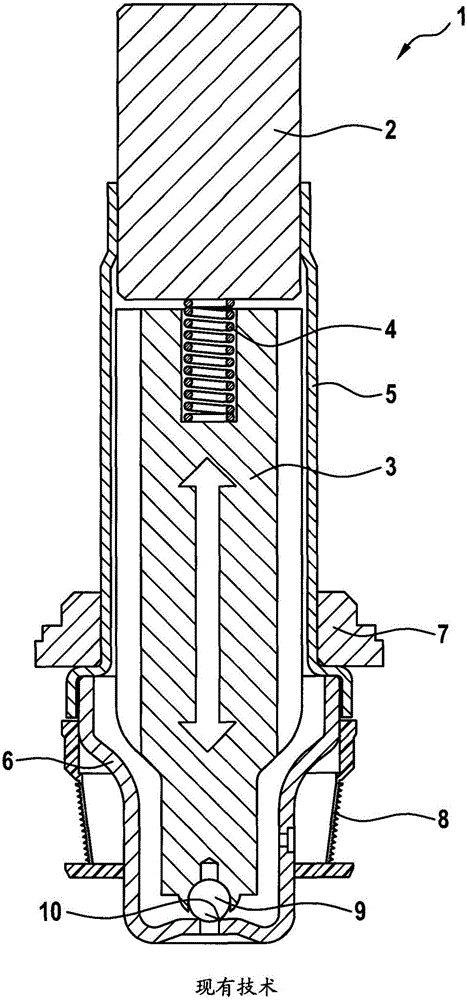
[0041] figure 1 A schematic sectional view of a prior art solenoid valve 1 for a hydraulic system of a vehicle is shown. Description 1 of such a solenoid valve can be seen in the description of the prior art.

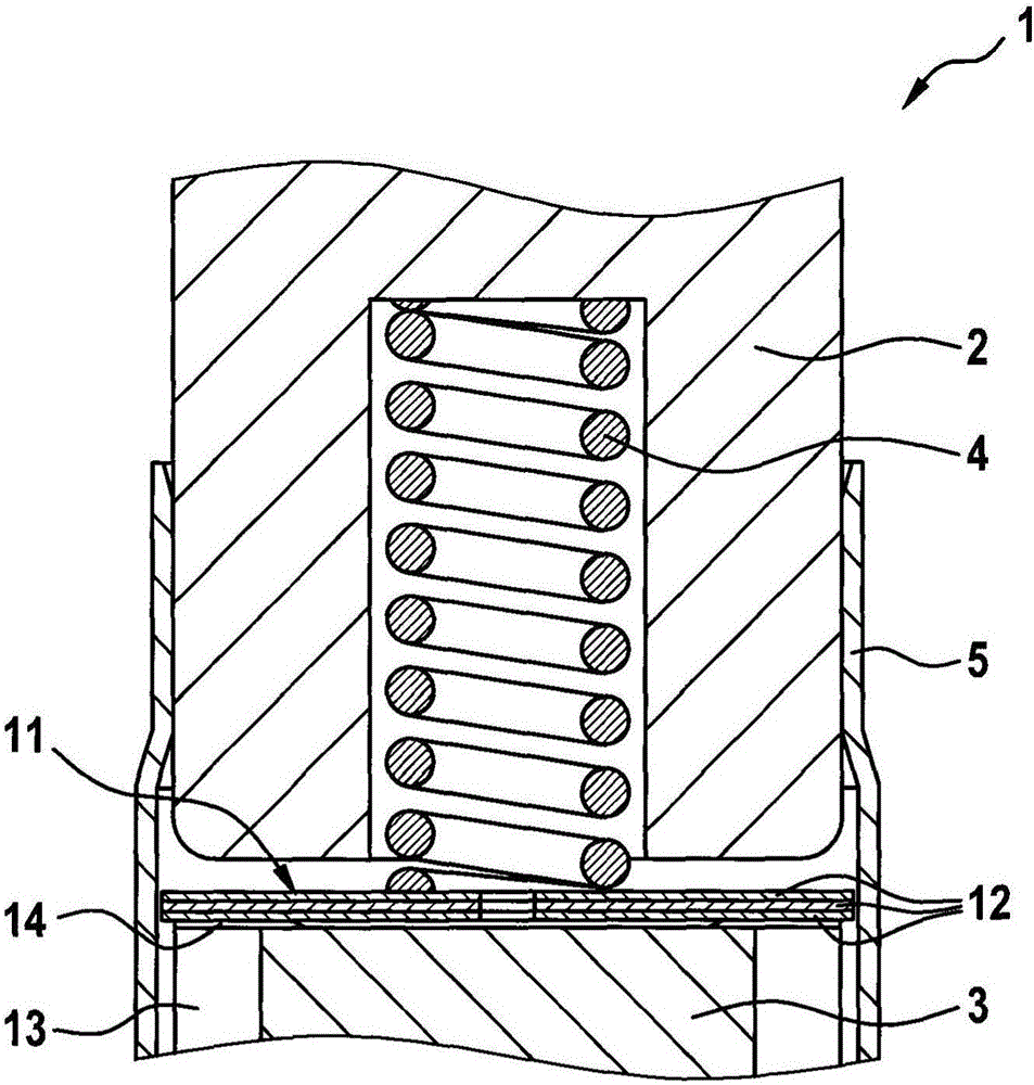
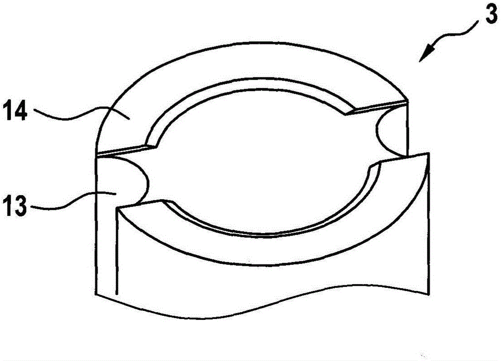
[0042] figure 2 A part of a cross-sectional view of an embodiment of a solenoid valve 1 with a mechanism 11 for hydraulic damping is shown. A specially designed spring washer 12 is used as the mechanism 11 . Three spring washers 12 are used in the embodiment shown. Here, the spring washer 12 , ie the mechanism 11 , is positioned directly on the armature 3 . In the radially outer region, the armature 3 has an armature groove 13 which is continuous over the entire length of the armature 3 . In the embodiment shown, two armature grooves 13 are formed. The armature 3 also has an armature step 14 in the outer region, on which the mechanism 11 rests directly. Due to the armature step 14 , a radially built-in cavity is formed between the mechanism 11 and the armature 3...


PUM


Abstract

The invention relates to an electrically closed solenoid valve. The solenoid valve is provided with a valve sleeve in which a pole core is fixedly arranged and an armature is arranged axially displaceably, wherein a pressure spring acts between the pole core and the armature in order to force a closing element cooperating with the armature into a valve seat. According to the invention, the valve is characterized in that a means for hydraulically damping the displacement of the armature is formed between the pole core and the armature.

Description

technical field [0001] The invention relates to a solenoid valve that is de-energized and has a valve sleeve in which a pole core is fixedly arranged, and in which an armature with a valve tip is arranged so as to be displaceable in the axial direction , wherein a coil spring acts between the pole core and the armature to press the valve top into the valve seat. Background technique [0002] Solenoid valves of the type mentioned at the outset are known from the prior art. Such a solenoid valve is, for example, the TTNr. 1267691803 de-energized solenoid valve MV09OS from Bosch in 2014, which is in figure 1 shown in . The solenoid valve 1 comprises an electromagnetic actuator comprising an energizable field coil (not shown) and a pole core 2 and acts on an armature 3 which is axially displaceable in valve sleeves 5 , 6 . The valve sleeves 5 , 6 can be designed as two-part valve sleeves with an upper valve sleeve 5 and a lower valve sleeve 6 . The valve sleeve 5 is position...

Claims


Application Information

Patent Timeline
IPC IPC(8): F16K31/06
CPCF16K31/0675F16K31/0662F16K31/0696H01F7/088H01F7/1607
Inventor M·安布罗西E·库尔兹N·阿拉策M·艾森劳尔
Owner ROBERT BOSCH GMBH
Why Eureka
Try Eureka