Ultrasonic engine jet pipe exhaust simulation test exhaust device

A technology of exhaust device and simulation test, which is applied in the direction of engine test, measurement device, internal combustion engine test, etc., and can solve the problems of huge structure, high cost, low efficiency, etc.

Active Publication Date: 2017-02-01
BEIJING AEROSPACE SANFA HIGH TECH
View PDF7 Cites 17 Cited by
  • Summary
  • Abstract
  • Description
  • Claims
  • Application Information

AI Technical Summary

Problems solved by technology

[0002] When simulating the high-altitude flight state of a supersonic engine on the ground, the engine is usually installed in the high-altitude simulation cabin first, and the high-altitude cabin is pumped with air extraction equipment so that the pressure in the high-altitude simulation cabin is the same as the environment where the engine is flying at high altitude. The pressure is the same, and then the engine is ignited, and the high-altitude flight simulation test is carried out. During the test, the pressure in the high-altitude simulation cabin must always be kept the same as the ambient pressure at the altitude of the engine when it is flying at high altitude. The gas is discharged from the high-altitude simulation cabin. In the prior art, an ejector or a vacuum tank is usually used for pumping air, and the pressure outside the high-altitude simulation cabin is usually 0.11MPa, while the ambient pressure at the flying height of the supersonic engine is only about 100% of the atmospheric pressure. 0.1 times, or even 0.01 times, the boost ratio of the exhaust system should reach 10 to 100, and the flow rate of the corresponding exhaust system inlet is as high as ten kilograms or even hundreds of kilograms per second. The flow rate depends only on the pressurization of the ejector, and three to four stages must be connected in series. If a vacuum tank is used, the volume of the vacuum tank must be as high as tens of thousands of cubic meters. It can be seen that no matter whether the ejector or the vacuum tank is used alone as the pumping Air equipment requires a huge structure, which is not only inefficient, but also very expensive; secondly, the engine test bench usually needs to perform high-altitude flight simulation for various engines, and different engines, engine size, engine tail nozzle size, engine The outlet flows are all different, and a set of air extraction equipment cannot meet the test requirements of various engines; No pressure) of the ejected airflow, the device that completes the ejected airflow and sucks the ejected airflow for mixing injection or delivery. Since the ejector has no moving parts, it is reliable and widely used in the exhaust system of the engine test bench; and The geometrical and positional relationship of the ejector that provides the ejector airflow and the blender of the blender is the key factor that determines the performance of the ejector. In the prior art, for the ejector of the exhaust system of the engine test bench, A mature and reasonable geometric and positional relationship between the ejecting part and the mixing part has not been formed, resulting in low ejecting performance of the ejector, reducing the efficiency of the test, and increasing the cost of the test

Method used


Image

  • Ultrasonic engine jet pipe exhaust simulation test exhaust device
  • Ultrasonic engine jet pipe exhaust simulation test exhaust device
  • Ultrasonic engine jet pipe exhaust simulation test exhaust device

Examples


Embodiment Construction

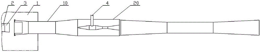
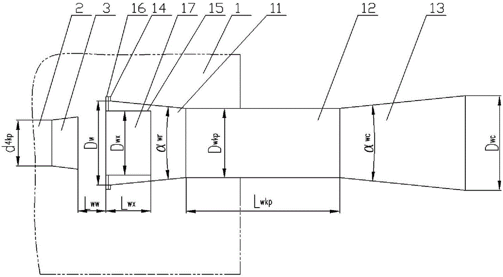
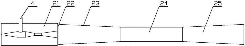
[0069] see Figure 1-5, an exhaust device for a supersonic engine exhaust nozzle exhaust simulation test, comprising a coaxial tail chamber 10 and an ejector 20 fixedly connected in sequence according to the engine tail nozzle 3 outlet exhaust flow direction; the tail chamber 10 It includes a fixed large tail chamber and a replaceable small tail chamber 15. According to the flow direction of the exhaust gas at the outlet of the engine tail nozzle 3, the fixed large tail chamber includes a coaxial and sequentially fixedly connected tail chamber convergence section 11, a tail chamber and other straight sections 12 and The tail chamber expansion section 13, the replaceable small tail chamber 15 is arranged in the tail chamber convergence section 11, and is coaxially fixedly connected with the tail chamber convergence section 11; the tail chamber convergence section 11, tail chamber and other straight sections 12 , the tail chamber expansion section 13 and the replaceable small ta...


PUM


Abstract

The invention discloses an ultrasonic engine jet pipe exhaust simulation test exhaust device. The device comprises poop houses and an injector which are coaxially and sequentially connected, wherein the poop houses comprise a large poop house and a replaceable small poop house, the large comprises a poop house convergence segment, a poop house linear segment and a poop house expansion segment which are coaxially connected, the replaceable small poop house is coaxially arranged in the poop house convergence segment, the injector comprises a low pressure house, a transition segment, a blending convergence segment, a blending linear segment and a blending expansion segment which are coaxially connected, the low pressure house is internally and coaxiallly connected with an injection flow input segment, an injection flow convergence segment and an injection flow linear segment, an outlet cross section of the low pressure house and an outlet cross section of an injection flow expansion segment are on one same vertical surface, an outlet of the poop house expansion segment and an inlet of the low pressure house are connected, the poop house convergence segment is arranged in a high-altitude boiler-plate, and the blending expansion segment is arranged outside the high-altitude boiler-plate. The device is advantaged in that test requirements of different ultrasonic engines simulating high-altitude flight states on the ground can be satisfied.

Description

technical field [0001] The invention relates to an exhaust device, in particular to an exhaust device for a supersonic engine tail nozzle exhaust simulation test. Background technique [0002] When simulating the high-altitude flight state of a supersonic engine on the ground, the engine is usually installed in the high-altitude simulation cabin first, and the high-altitude cabin is pumped with air extraction equipment so that the pressure in the high-altitude simulation cabin is the same as the environment where the engine is flying at high altitude. The pressure is the same, and then the engine is ignited, and the high-altitude flight simulation test is carried out. During the test, the pressure in the high-altitude simulation cabin must always be kept the same as the ambient pressure at the altitude of the engine when it is flying at high altitude. The gas is discharged from the high-altitude simulation cabin. In the prior art, an ejector or a vacuum tank is usually used ...

Claims


Application Information

Patent Timeline
Patent Type & Authority Applications(China)
IPC IPC(8): G01M15/10G01M13/00
CPCG01M13/00G01M15/106
Inventor 赵聚均孙建王文彬朱红林
Owner BEIJING AEROSPACE SANFA HIGH TECH
Why Eureka
Try Eureka