Wine output structure of plastic wine bucket

A wine barrel and plastic technology, applied in the field of wine equipment, can solve the problems of poor sealing performance, difficult installation, poor stability, etc., to achieve the effect of ensuring sealing and convenient and labor-saving installation process

Active Publication Date: 2017-02-08
TALOS TECH CORP
View PDF7 Cites 11 Cited by
  • Summary
  • Abstract
  • Description
  • Claims
  • Application Information

AI Technical Summary

Problems solved by technology

However, the wine spear needs to overcome the spring resistance and fix the sealing assembly to the wine outlet pipe when installing the core, which is difficult to install. If the

Method used


Image

  • Wine output structure of plastic wine bucket
  • Wine output structure of plastic wine bucket
  • Wine output structure of plastic wine bucket

Examples


Embodiment 1

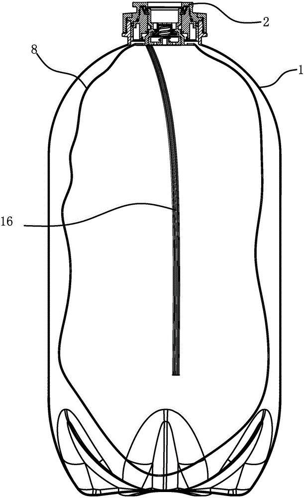
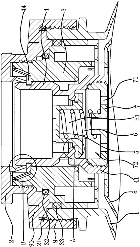
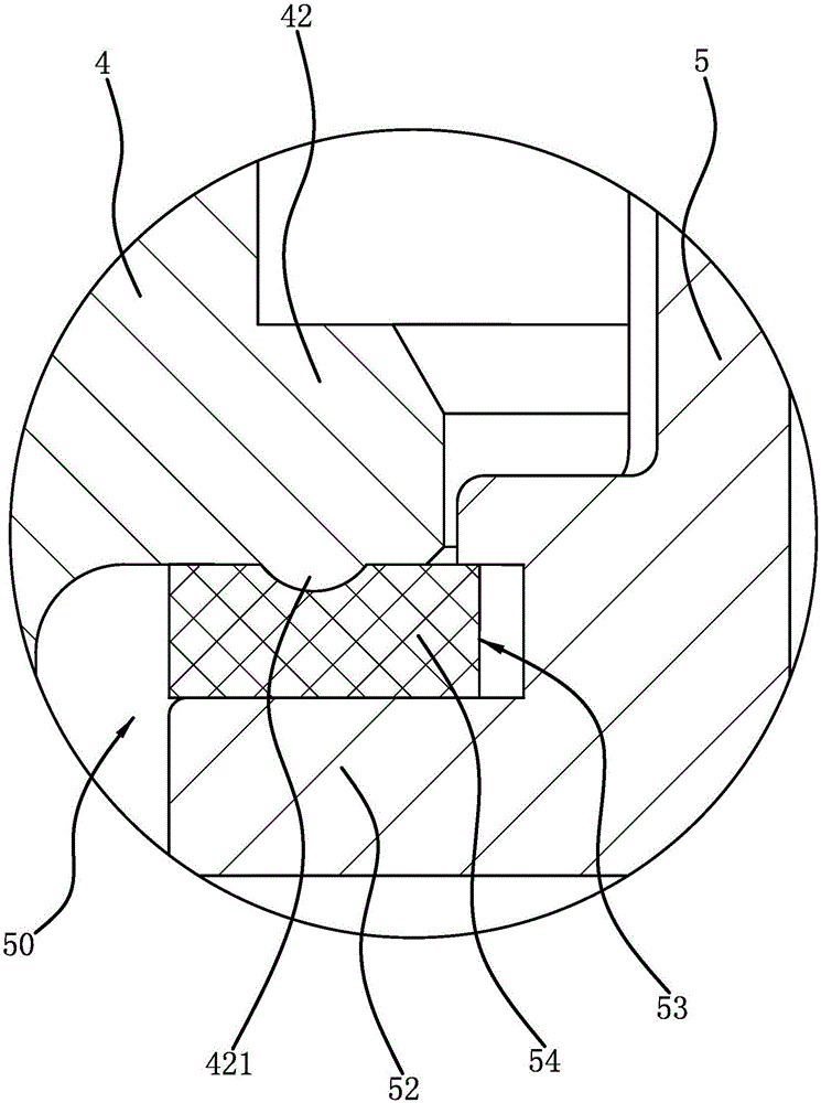
[0056] Such as figure 1 , figure 2 As shown, a wine output structure of a plastic wine barrel, the plastic wine barrel includes a barrel body 1, the upper end of the barrel body 1 is a barrel mouth, and the barrel mouth has a cylindrical side wall, and the barrel mouth of the barrel body 1 is fixedly connected with a The wine spear head 2 and the guide sleeve 3, the guide sleeve 3 is inserted into the barrel mouth of the barrel body 1 and is located in the wine spear head 2, the two ends of the joint 4 pass through and are slidably arranged in the guide sleeve 3, and the flexible bag 8 is connected to the lower end of the joint 4 , for wine. The wine dispensing structure includes a pressure cap 7 and a valve core 5. The valve core 5 is slidingly arranged in the joint 4. The pressure cap 7 is provided with a wine passage hole 71, which is detachably connected to the lower end of the joint 4. The valve core 5 is located in the pressure cap 7. On the top, there is a spring 6 b...

Embodiment 2

[0062] The wine outlet structure of the plastic wine barrel is basically the same as that of Embodiment 1, the difference is that Figure 10 As shown, the lower end surface of the valve core 5 has a mounting hole 51, and the upper end surface of the pressure cap 7 has a circular limiting groove 73, the wine hole 71 is distributed around the limiting groove 73, and the upper end of the spring 6 presses On the bottom surface of the mounting hole 51 , the lower end is pressed against the limiting groove 73 of the pressing cap 7 .

Embodiment 3

[0064] The wine outlet structure of the plastic wine barrel is basically the same as that of Embodiment 1, the difference is that Figure 11 As shown, the spring 6 is straight and has a large diameter. The wine hole 71 is set at the center of the pressure cap 7. The upper end of the spring 6 is pressed against the lower end surface of the supporting convex edge 52, and the lower end is pressed against the pressure cap 7. The edge of the inner bottom surface makes the support of the spring 6 to the valve core 5 more stable.


PUM


Abstract

The invention provides a wine output structure of a plastic wine bucket, and belongs to the technical field of wine output structures of plastic wine buckets. The technical problems that an existing wine bucket is inconvenient to mount, and poor in wine output stability are solved. The plastic wine bucket comprises a bucket body, a wine spearhead and a guide sleeve are fixedly connected to a bucket opening of the bucket body, the guide sleeve is located in the wine spearhead, a joint with two through ends is connected in the guide sleeve, the lower end of the joint is connected with a flexible bag, and the wine output structure comprises a pressing cap and a valve element; and the valve element is arranged in the joint and can vertically move, the pressing cap is located at the lower end of the joint, an elastic part capable of enabling the valve element to act on the joint and forming seal with the joint is arranged between the valve element and the pressing cap, the pressing cap is detachably connected with the joint, and a wine passing hole is formed in the pressing cap. The structure has the beneficial effects of being convenient to mount and good in wine output effect.

Description

technical field [0001] The invention belongs to the technical field of wine equipment and relates to a wine outlet structure of a plastic wine barrel. Background technique [0002] A wine barrel is a tool for holding wine. Generally, a wine spear is arranged at the barrel mouth of the wine barrel, and the wine spear cooperates with the dispenser to realize pressing out the wine in the wine barrel. At present, the wine barrels commonly used in the market are all metal wine barrels. Metal wine barrels are expensive and troublesome to clean. Generally, merchants do not have special equipment for cleaning metal wine barrels. Therefore, after the wine in the barrel is used up, , It is necessary to transport the empty wine barrels to the factory for cleaning, which increases the cost of transportation back and forth. When this kind of wine barrel is pressed out, the gas is directly filled into the inside of the wine barrel, and the pressure of the gas is applied to the surface of...

Claims


Application Information

Patent Timeline
IPC IPC(8): B65D47/06B65D77/06B65D85/72
CPCB65D47/06B65D77/06B65D85/72B65D2547/063
Inventor 邱迪林
Owner TALOS TECH CORP
Why Eureka
Try Eureka