A Counter-wheel Spinning Device for Forming Cylindrical Parts with Different Diameters and Wall Thicknesses

A cylindrical part and wheel-aligning technology, which is applied in the field of wheel-aligning spinning devices, can solve the problems of long manufacturing cycle, poor versatility, and high mold cost, and achieve the effect of improving spinning accuracy

Active Publication Date: 2018-03-16
HARBIN INST OF TECH
View PDF5 Cites 0 Cited by
  • Summary
  • Abstract
  • Description
  • Claims
  • Application Information

AI Technical Summary

Problems solved by technology

[0003] The purpose of the present invention is to solve the problems of high mold cost, poor versatility and long manufacturing cycle of the existing molded spinning equipment, and to provide a counter-wheel spinning device for forming cylindrical parts with different diameters and wall thicknesses

Method used


Image

  • A Counter-wheel Spinning Device for Forming Cylindrical Parts with Different Diameters and Wall Thicknesses
  • A Counter-wheel Spinning Device for Forming Cylindrical Parts with Different Diameters and Wall Thicknesses
  • A Counter-wheel Spinning Device for Forming Cylindrical Parts with Different Diameters and Wall Thicknesses

Examples


specific Embodiment approach 1

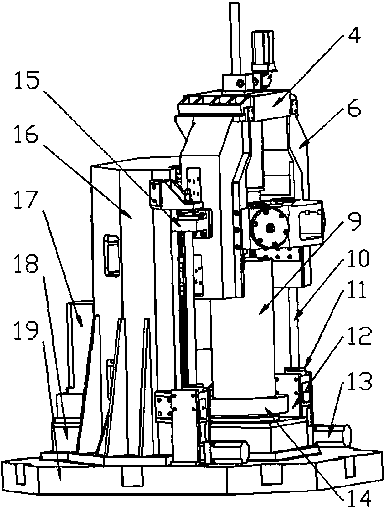
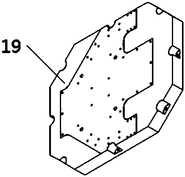
[0021] Specific embodiment one: combine 1 to Figure 24 Describe this embodiment. A counter-wheel spinning device for forming cylindrical parts with different diameters and wall thicknesses in this embodiment includes a base 19, a gear box 18, a spindle motor 17, a frame 16, and two nut connection seats. 15. Eight-jaw chuck 14, two sets of lifting components, external rotation components, internal rotation components, two main carriages 6 and upper beam 4,

[0022] Frame 16 is installed on the base 19, and gear box 18 passes through frame 16 and is installed on the base 19, and main shaft motor 17 is connected with the input end of gear box 18, and eight-jaw chuck 14 is installed in the output end of gear box 18, Two groups of lifting assemblies are respectively installed on both sides of the frame 16, and the upper ends of the two groups of lifting assemblies are connected with the upper ends of the frame 16. One side of each silk nut connecting seat 15 is connected with a mai...

specific Embodiment approach 2

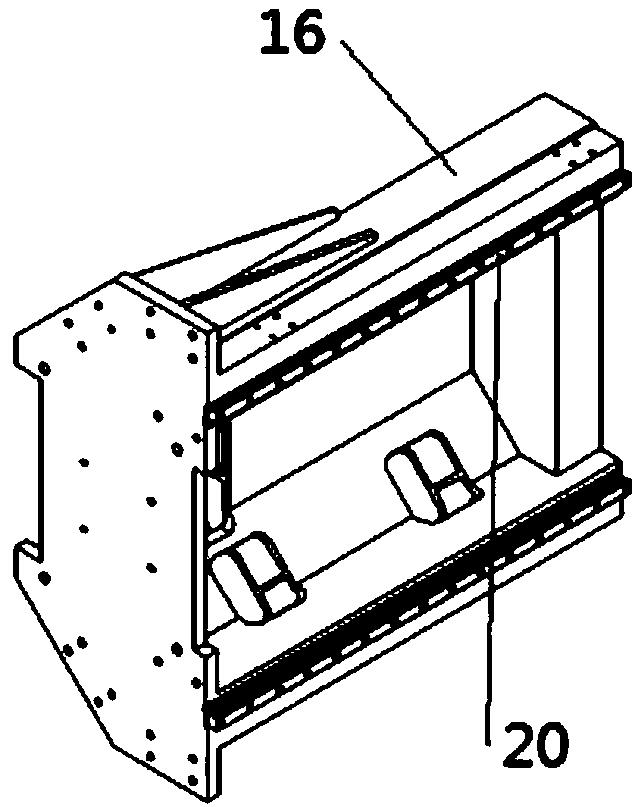
[0023] Specific implementation mode two: combination image 3 To illustrate this embodiment, a guide rail 20 is installed on both sides of the frame 16 of this embodiment, and the other side of each nut connector 15 is slidably mounted on the guide rail 20 on one side of the frame 16 . It is convenient for the main carriage 6 to slide flexibly on the guide rail 20, and other components and connections are the same as those in the first embodiment.

specific Embodiment approach 3

[0024] Specific implementation mode three: combination figure 1 Illustrate this embodiment, each group of lifting assembly of this embodiment comprises lifting motor 13, bearing block connecting plate 12, lead screw bearing block 11 and lifting lead screw 10, and bearing seat connecting plate 12 is installed on the base 19, and lead screw bearing Seat 11 is installed on the bearing block connecting plate 12, and one end of the lifting screw 10 is connected with the screw bearing block 11, and the screw nut connecting seat 15 is installed on the lifting screw 10, and the other end of the lifting screw 10 is connected to the machine through a connector. The frame 16 is connected, and the lifting motor 13 transmits the power output to the lifting screw 10 through the transmission member. The transmission part adopts worm gear or bevel gear to transmit power. It is convenient to drive the main carriage 6 to slide flexibly on the guide rail 20. Other compositions and connections ...


PUM


Abstract

The invention discloses an opposite roller spinning device for forming tube-shaped pieces of different diameters and wall thicknesses, and relates to opposite roller spinning devices. The opposite roller spinning device aims to solve the problems that existing mold spinning equipment is high in mold cost, poor in universality and long in manufacturing cycle. According to the opposite roller spinning device for forming the tube-shaped pieces of different diameters and wall thicknesses, a rack is installed on a base, and a gear case is installed on the base; a spindle motor is connected with the input end of the gear case, and an eight-claw chuck is installed at the output end of the gear case; two lifting assemblies are installed at the two sides of the rack correspondingly; two screw nut connecting bases are installed on screw rods of one lifting assembly separately; one side of each screw nut connecting base is connected with a main sliding frame, and the other side of each screw nut connecting base is installed at one side of the rack in a sliding mode; the two main sliding frames are connected through an upper cross beam; and an inner rotation assembly penetrates through the upper cross beam to extend downwards to the position between the two main sliding frames, and an outer rotation assembly is installed between the two main sliding frames. The opposite roller spinning device is used for spinning thin-walled tube-shaped pieces.

Description

technical field [0001] The invention relates to a counter-wheel spinning device, in particular to a counter-wheel spinning device for forming cylindrical parts with different diameters and wall thicknesses. Background technique [0002] Wheel spinning is a kind of powerful spinning technology, which is developed on the basis of traditional spinning with mandrel. It uses a pair or several pairs of inner and outer rotary wheels to perform plastic processing on the inner and outer surfaces of the workpiece at the same time. Since there is no mandrel and the number and shape of the wheel pairs can be adjusted according to the actual situation, the wheel spinning has the following advantages: by adjusting the radial distance of the wheel pairs, pipe fittings with any diameter and different thickness within a certain range can be processed, thus reducing The production cost of the mandrel is reduced; in the case of the same initial wall thickness and deformation degree, compared ...

Claims


Application Information

Patent Timeline
Patent Type & Authority Patents(China)
IPC IPC(8): B21D22/14
CPCB21D22/14
Inventor 徐文臣单德彬王森鹏蒋绪伟王光男杨川
Owner HARBIN INST OF TECH
Why Eureka
Try Eureka