A pair of wheel spinning equipment for forming large thin-walled cylindrical parts

A technology of spinning equipment and thin-walled cylinder, which is applied in the field of wheel spinning equipment for forming large-scale thin-walled cylindrical parts, can solve the problems of high cost, poor versatility, long manufacturing cycle, etc. Tangential force, the effect of improving the rigidity of the screw

Active Publication Date: 2018-04-24
HARBIN INST OF TECH
View PDF6 Cites 0 Cited by
  • Summary
  • Abstract
  • Description
  • Claims
  • Application Information

AI Technical Summary

Problems solved by technology

[0003] The purpose of the present invention is to solve the problems of high cost, poor versatility and long manufacturing cycle due to the need for core molds in the existing molded spinning equipment, and to provide a method for forming large thin-walled cylindrical parts. equipment

Method used


Image

  • A pair of wheel spinning equipment for forming large thin-walled cylindrical parts
  • A pair of wheel spinning equipment for forming large thin-walled cylindrical parts
  • A pair of wheel spinning equipment for forming large thin-walled cylindrical parts

Examples


specific Embodiment approach 1

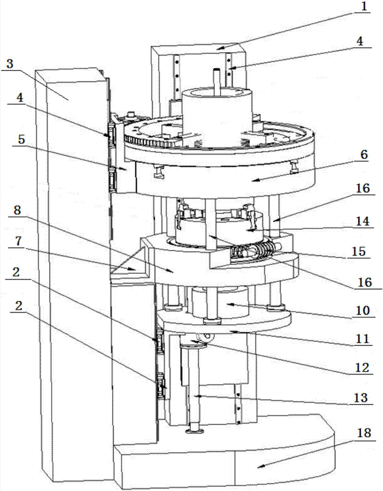
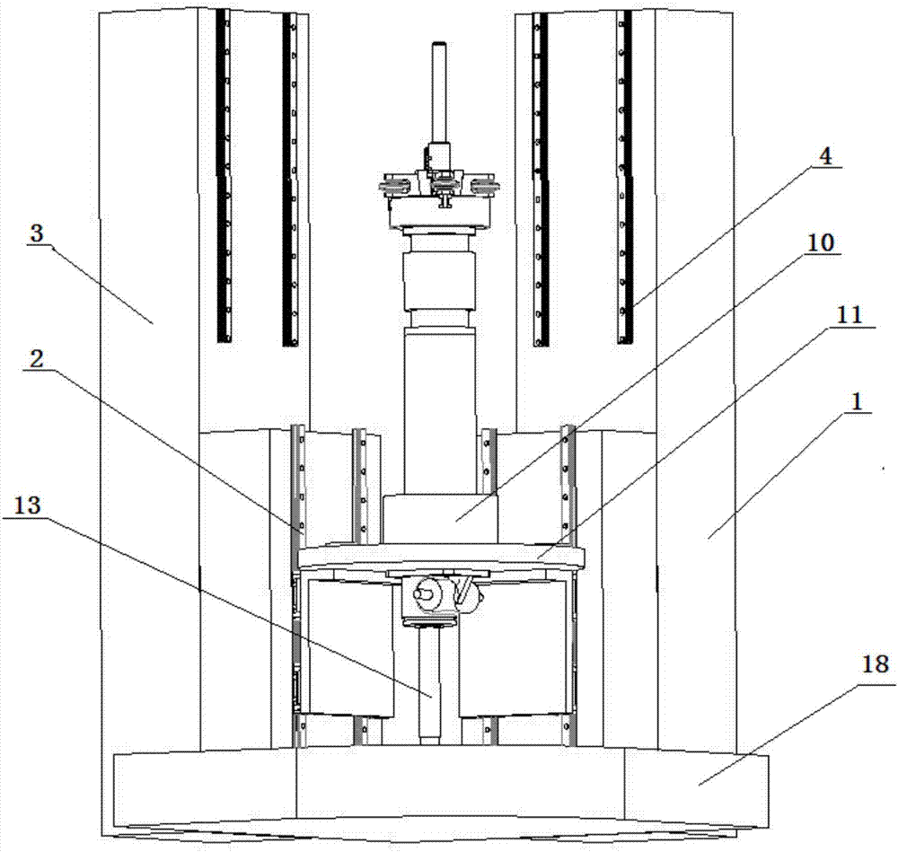
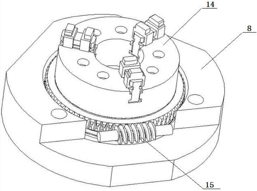
[0030] Specific embodiment one: combine 1 to Figure 14 Describe this embodiment, a wheel spinning equipment for forming large thin-walled cylindrical parts in this embodiment includes a first vertical frame 1, an inner rotation guide rail 2, a second vertical frame 3, an outer rotation guide rail 4. Outer rotation mechanism fixing seat 5, outer rotating disk 6, chuck base fixing seat 7, chuck base 8, base 18, bottom plate 11, lifting screw 13, lifting motor 12, inner rotation device fixing seat 10, Three-jaw chuck 14, worm gear assembly 15, multiple pull rods 16, internal rotation device and external rotation device;

[0031] The first vertical frame 1 and the second vertical frame 3 are installed on the base 18 at 90° with each other, and the inner rotation guide rail 2 is installed on the bottom of the first vertical frame 1 and the second vertical frame 3. The rotary guide rail 4 is installed on the top of the first vertical frame 1 and the second vertical frame 3, and th...

specific Embodiment approach 2

[0033] Specific implementation mode two: combination Figure 4 to Figure 9 Describe this embodiment, a kind of internal rotation device used for large-scale thin-walled tubular part counter-wheel spinning equipment in this embodiment includes internal rotation wheel seat guide sleeve A-1-1, internal rotation wedge guide sleeve A -1-4, inner rotation transition sleeve A-1-5, inner rotation upper beam A-1-6, inner rotation feed screw A-1-7, inner rotation motor A-1-8, inner rotation deceleration Device A-1-9, internal rotation cone wedge A-2-2, multiple internal rotation wheel seats A-2-3, multiple internal rotation wheels A-2-4 and multiple internal rotation wheel shafts A -3-2.

[0034] The inner-rotating conical wedge A-2-2 is set on the inner-rotating feed screw A-1-7, and a plurality of inner-rotating wheel seats A-2-3 are evenly distributed in a ring and installed on the inner-rotating conical wedge A On -2-2, each internal rotation wheel seat A-2-3 is vertically rotatab...

specific Embodiment approach 3

[0036] Specific implementation mode three: combination Figure 4 to Figure 9 Describe this embodiment, the inner turning wheel seat A-2-3 of this embodiment of this embodiment is a U-shaped structure, the upper and lower ends of the inner turning wheel A-2-4 are fitted with the tapered roller bearings at the head and tail sections of the turning wheel shaft A-3-3 constitutes an interference fit. Such an arrangement facilitates the provision of a spinning working environment and space for the rotary wheel.


PUM


Abstract

The invention relates to opposite roller spinning equipment, in particular to opposite roller spinning equipment for forming a large thin-walled cylindrical part, and aims to solve the problems that existing die spinning equipment is high in cost, poor in universality and long in manufacturing period as a core die is needed. A chuck substrate fixing base is installed on a rack between an internal rotation guide rail and an external rotation guide rail, a chuck substrate is installed on the chuck substrate fixing base, an external rotation mechanism fixing base is installed on the external rotation guide rail in a sliding mode, and an external rotation disc is installed on the external rotation mechanism fixing base; a bottom plate is installed on an internal rotation guide rail, a lifting motor is installed at the lower end of the bottom plate, one end of a lifting lead screw penetrates through the bottom plate, and the other end of the lifting lead screw is connected with a base; an internal rotation device fixing base is installed on the bottom plate, a worm and gear assembly is installed on the chuck substrate, a three-claw chuck is installed on the worm and gear assembly, multiple pull rods are connected with the external rotation disc, the chuck substrate and the base, an internal rotation device is installed in the internal rotation device fixing base, and the external rotation device is installed in the external rotation disc. The opposite roller spinning equipment is suitable for carrying out opposite roller spinning on the large thin-walled cylindrical part.

Description

technical field [0001] The invention relates to a counter-wheel spinning equipment, in particular to a counter-wheel spinning equipment for forming large thin-walled cylindrical parts. Background technique [0002] Through the comparison and analysis of several existing large-diameter and thin-walled cylinder forming processes, a process for ultra-large-diameter thin-walled cylinders—counterwheel spinning is proposed. In this process, the traditional mandrel is replaced by a rotary wheel, and the inner and outer surfaces of the cylindrical part are formed simultaneously, without being limited by the diameter, wall thickness and length of the large-sized cylinder. It is of great significance for the production of ultra-large-diameter thin-walled cylinders, and is the main method for forming large-diameter cylinders in the future. Especially in the manufacture of large-diameter thin-walled cylindrical parts, the existing molded spinning equipment has the problems of high cost...

Claims


Application Information

Patent Timeline
Patent Type & Authority Patents(China)
IPC IPC(8): B21D22/14
CPCB21D22/14
Inventor 徐文臣单德彬王森鹏杨川蒋绪伟陈宇
Owner HARBIN INST OF TECH
Why Eureka
Try Eureka