Supercharge Your Innovation With Domain-Expert AI Agents!

Rotor bearing sleeving press device

A bearing and rotor technology, applied in metal processing, metal processing equipment, manufacturing tools, etc., can solve problems such as low efficiency, and achieve the effect of ensuring the quality of casing pressure and improving work efficiency

Inactive Publication Date: 2017-02-15
德力电机有限公司
View PDF6 Cites 1 Cited by
  • Summary
  • Abstract
  • Description
  • Claims
  • Application Information

AI Technical Summary

Problems solved by technology

This method is inefficient. In order to improve the working efficiency of bearing sleeve pressure, it is necessary to design a sleeve pressure device.

Method used


Image

  • Rotor bearing sleeving press device
  • Rotor bearing sleeving press device

Examples


Embodiment Construction

[0009] The specific embodiment of the present invention will now be described in conjunction with the accompanying drawings.

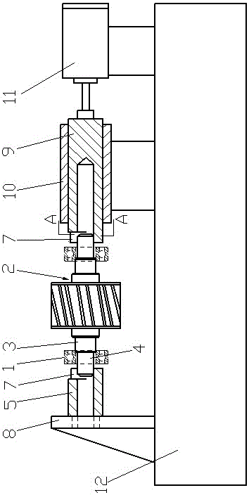
[0010] A sleeve pressure device for rotor bearings (see figure 1 ), used to press the bearing 1 sleeve on the main shaft of the motor rotor. The sleeve pressure device of the rotor bearing includes a base 12, a first support 8 installed on the left side of the base, a second support 10 installed on the right side of the base, and a positioning sleeve 5 is fixed on the first support. A tappet 9 is provided on the second support, and the tappet is slidingly fitted with the long through hole on the second support, and the positioning sleeve is coaxial with the tappet; the maximum distance between the right side of the positioning sleeve and the left side of the tappet is slightly greater than The length of the motor rotor main shaft 2, the hole of the positioning sleeve matches the connecting part 4 at the left end of the motor rotor main shaft; the left...


PUM


Abstract

Disclosed is a rotor bearing sleeving press device. The rotor bearing sleeving press device is used for pressing bearings on a spindle of a motor rotor in a sleeving mode. The rotor bearing sleeving press device comprises a first supporting base (8) and a second supporting base (10), wherein the first supporting base is installed on the left side of a base, and the second supporting base is installed on the right side of the base. A locating sleeve (5) is fixedly arranged on the first supporting base, a tappet rod (9) is arranged on the second supporting base, the tappet rod and a long through hole formed in the second supporting base are in sliding fit, and the locating sleeve and the tappet rod are coaxial. The maximum distance between the right side of the locating sleeve and the left side of the tappet rod is slightly larger than the length of the motor rotor spindle (2), and a hole of the locating sleeve is matched with a connecting portion (4) at the left end of the motor rotor spindle. A blind hole is formed in the left end of the tappet rod and matched with a connecting portion at the right end of the motor rotor spindle. The locating sleeve and the tappet rod are coaxial, and the right end of the tappet rod is connected with an oil cylinder (11). The rotor bearing sleeving press device has the advantages that due to the fact that the bearings at the two ends of the motor rotor spindle can be pressed in a sleeving mode at the same time, the working efficiency is improved; and due to the fact that the force borne by the ends of the bearings in the sleeving press process is uniform, the sleeving press quality is guaranteed.

Description

technical field [0001] The invention relates to a sleeve pressing device of a rotor bearing, which is used for pressing the bearing sleeve on the main shaft of the motor rotor. Background technique [0002] The structure of the motor rotor main shaft 2 is that the middle section of the motor rotor main shaft is an iron core part with an iron core, the two sides of the iron core part are bearing parts 3 with bearings, and the outer side of the bearing part is the connection part between the motor rotor main shaft and the outside 4, wherein the diameter of the core part is larger than the diameter of the bearing part, and the diameter of the bearing part is larger than the diameter of the connecting part. The method of pressing the bearing on the main shaft is to first press the bearing at one end of the main shaft, and then press the bearing at the other end of the main shaft. This kind of method is inefficient, and in order to improve the working efficiency of the bushing p...

Claims


Application Information

Patent Timeline
IPC IPC(8): B23P19/027
CPCB23P19/027
Inventor 钱春
Owner 德力电机有限公司
Features
  • R&D
  • Intellectual Property
  • Life Sciences
  • Materials
  • Tech Scout
  • Unparalleled Data Quality
  • Higher Quality Content
  • 60% Fewer Hallucinations
Learn More