Eureka AIR delivers breakthrough ideas for toughest innovation challenges, trusted by R&D personnel around the world.

A solution recovery device for a machine tool and the machine tool

A solution recovery and machine tool technology, applied in positioning devices, metal processing machine parts, manufacturing tools, etc., can solve the problems of increasing solution resource costs, solution waste, entering the pipeline and being pulled out of the machine tool, etc.

Active Publication Date: 2019-07-09
GUANGDONG EVERWIN PRECISION TECH
View PDF5 Cites 0 Cited by
  • Summary
  • Abstract
  • Description
  • Claims
  • Application Information

AI Technical Summary

Problems solved by technology

However, after long-term work, the sealing ring at the joint between the vacuum fixture and the pipeline may be leaked due to partial rupture or deformation.
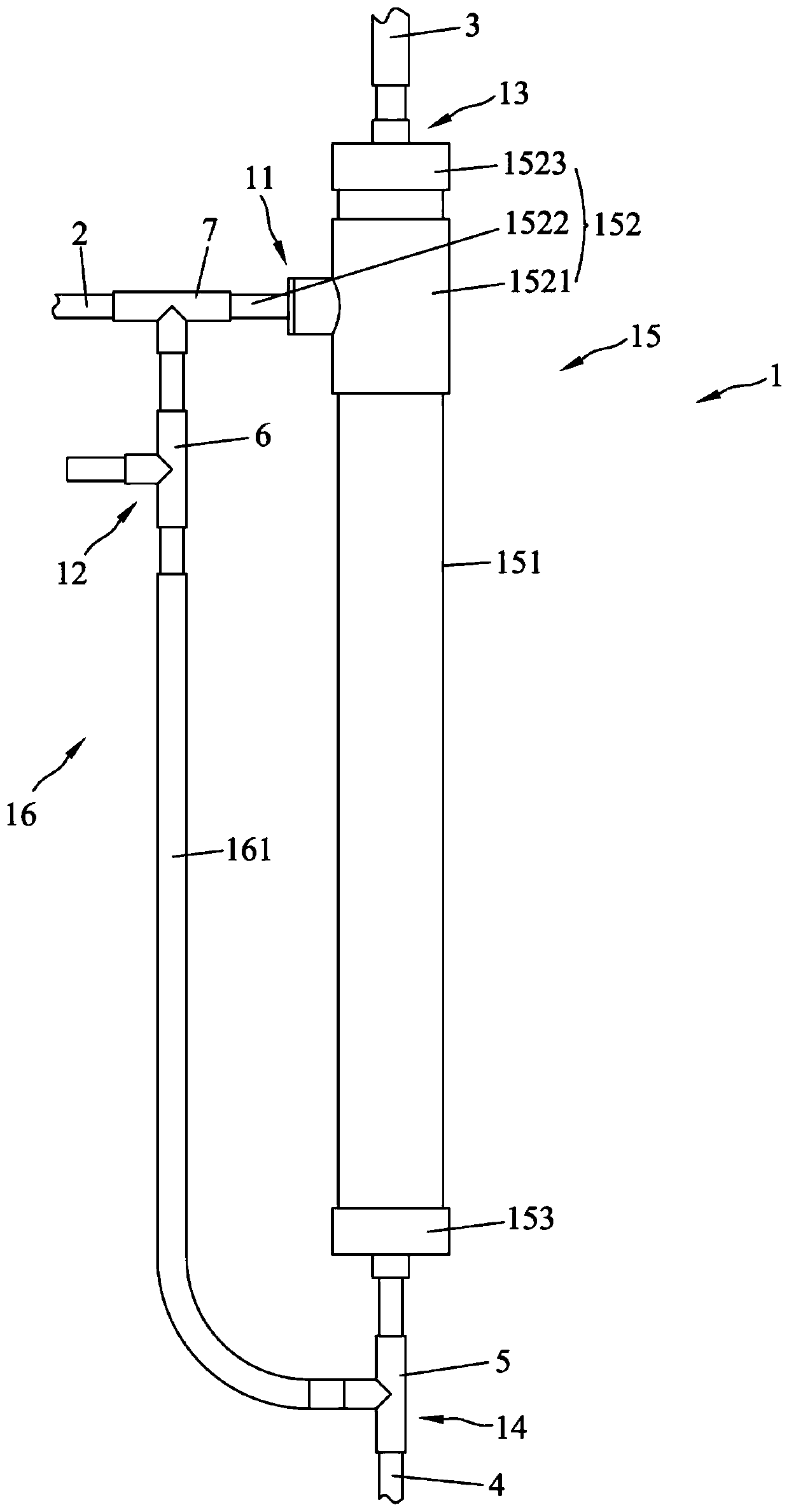
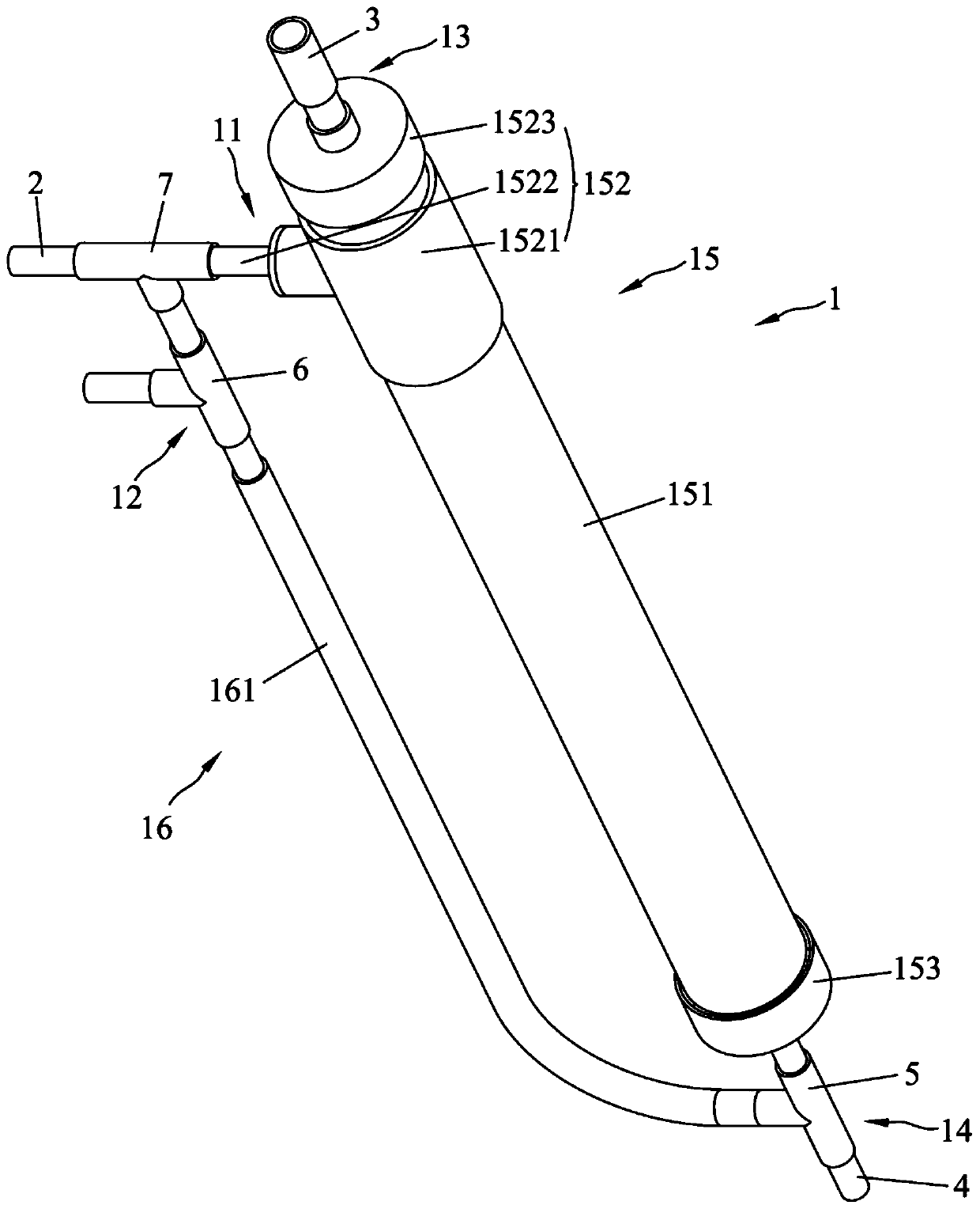
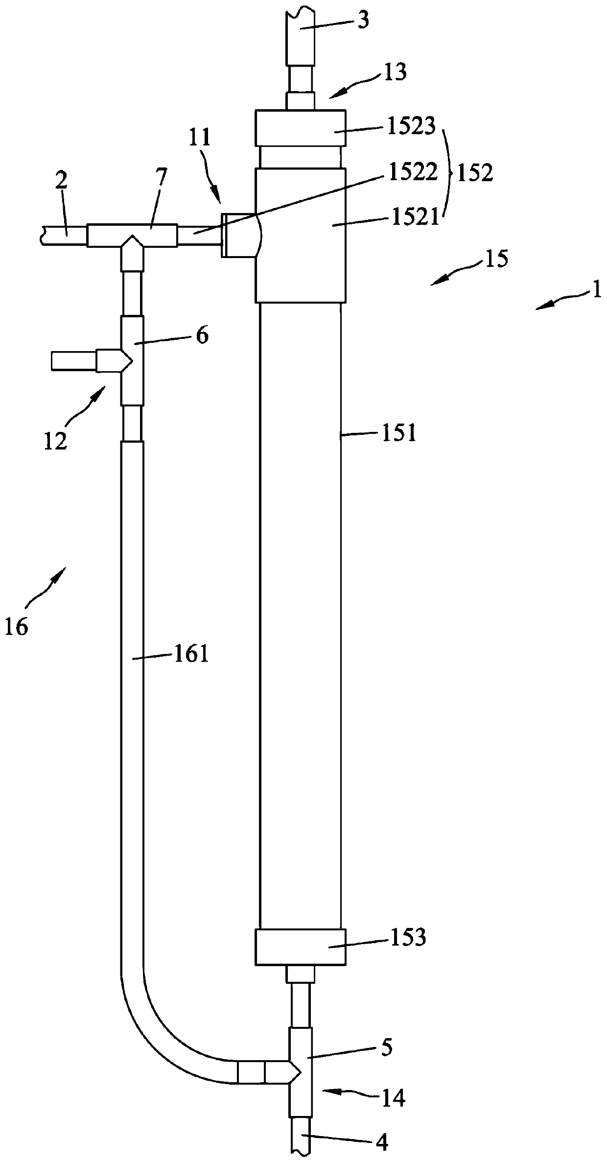
At this time, under the action of negative pressure, the solution in the workpiece processing area (such as the coolant sprayed on the workpiece) will enter the pipeline through the vent and be drawn away from the machine tool, and the solution drawn out of the machine tool cannot be recycled.
In this way, on the one hand, it will cause waste of solution and increase the cost of solution resources; on the other hand, it takes time to manually replenish the solution in the solution storage area (such as the oil tank) of the machine tool, thereby increasing labor costs

Method used


Image

  • A solution recovery device for a machine tool and the machine tool
  • A solution recovery device for a machine tool and the machine tool
  • A solution recovery device for a machine tool and the machine tool

Examples


Embodiment Construction

[0017] The technical solutions in the embodiments of the present invention will be clearly and completely described below in conjunction with the accompanying drawings. Apparently, the described embodiments are only part of the embodiments of the present invention, not all of them. Based on the embodiments of the present invention, all other embodiments obtained by persons of ordinary skill in the art without creative efforts fall within the protection scope of the present invention.

[0018] It should be noted that if the embodiment of the present invention involves directional indications (such as up, down, left, right, front, back, top, bottom, inside, outside, vertical, horizontal, vertical, counterclockwise, clockwise, circumferential direction, radial direction, axial direction...), the directional indication is only used to explain the relative positional relationship, movement conditions, etc. When a change occurs, the directional indication changes accordingly.

[00...


PUM


Abstract

The invention discloses a solution recovery device for a machine tool and the machine tool. The solution recovery device comprises a container, a first switch valve and a second switch valve. A containing space for containing a solution is hollowly formed in the container. A first gas inlet, a second gas inlet, a gas outlet and a liquid outlet, all of which communicate with the containing space are formed in the container. The first gas inlet is connected with a vacuum fixture in a communicating manner. The gas outlet is connected with a vacuum generator in a communicating manner. The gas outlet and the second gas inlet are higher than the liquid outlet. The first switch valve is used for controlling connection and disconnection of the liquid outlet. The second switch valve is used for controlling connection and disconnection of the second gas inlet. According to the solution recovery device for the machine tool and the machine tool, when the solution stored in the containing space needs to be recovered, vacuumizing operation on the containing space by the vacuum generator can be stopped firstly, the first switch valve and the second switch valve are opened, then external air enters the containing space from the second gas inlet quickly, the solution flows out of the container from the liquid outlet due to the gravity for recovery and reutilization, the waste of the solution is avoided, and therefore the cost of the solution resource is lowered.

Description

technical field [0001] The invention relates to the technical field of machine tool processing, in particular to a solution recovery device of a machine tool and the machine tool. Background technique [0002] Many machine tools (especially numerically controlled machine tools (CNC)) are equipped with vacuum fixtures for clamping workpieces. The vacuum fixtures are connected to vacuum generators (usually vacuum pumps) through pipelines, and sealing rings are set at the connections between vacuum fixtures and pipelines. , On the one hand, it can ensure that sufficient negative pressure is provided for the vacuum fixture during the working process, and on the other hand, it can prevent liquid from entering the pipeline during the working process. When working, the vacuum generator evacuates and generates negative pressure to clamp the workpiece on the corresponding parts of the vacuum fixture, which is convenient for the subsequent positioning and processing of the workpiece. ...

Claims


Application Information

Patent Timeline
Patent Type & Authority Patents(China)
IPC IPC(8): B23Q11/00B23Q3/08
CPCB23Q3/088B23Q11/00
Inventor 林贵灵
Owner GUANGDONG EVERWIN PRECISION TECH
Why Eureka
Eureka Blog
Learn More