
Auxiliary support device for processing large thin-walled components and using method

A technology of auxiliary support and thin-walled components, which is applied in metal processing and other directions, can solve the problems of rigidity reduction, processing deformation, and lower hole-making efficiency, so as to avoid the influence of human factors, stabilize the quality of hole-making processing, and improve the manufacturing efficiency. Effect of hole machining efficiency

Active Publication Date: 2018-01-09
SHENYANG AEROSPACE UNIVERSITY
View PDF7 Cites 0 Cited by
  • Summary
  • Abstract
  • Description
  • Claims
  • Application Information

AI Technical Summary

Problems solved by technology

[0005] As the hole-making depth increases, the stiffness of large thin-walled components at the hole-making position will gradually decrease. At this time, under the action of cutting force, delamination damage will occur at the hole-making position, which seriously reduces the large-scale Hole-making precision of thin-walled components
[0006] In order to avoid processing deformation, vibration and delamination damage during the hole-making process, at present, manual methods are often used to implement auxiliary tightening measures with a high degree of freedom at the hole-making position, although the processing deformation, vibration chatter and delamination damage, but it also lowers the efficiency of hole-making processing, and the quality of hole-making processing is very unstable due to the influence of human factors.

Method used


Image

  • Auxiliary support device for processing large thin-walled components and using method
  • Auxiliary support device for processing large thin-walled components and using method
  • Auxiliary support device for processing large thin-walled components and using method

Examples


Embodiment Construction

[0037] The present invention will be further described in detail below in conjunction with the accompanying drawings and specific embodiments.

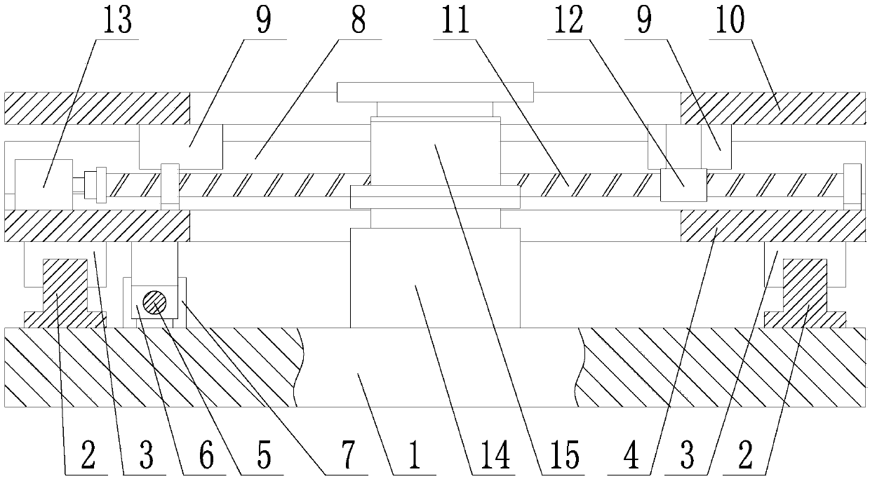
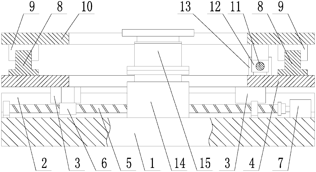
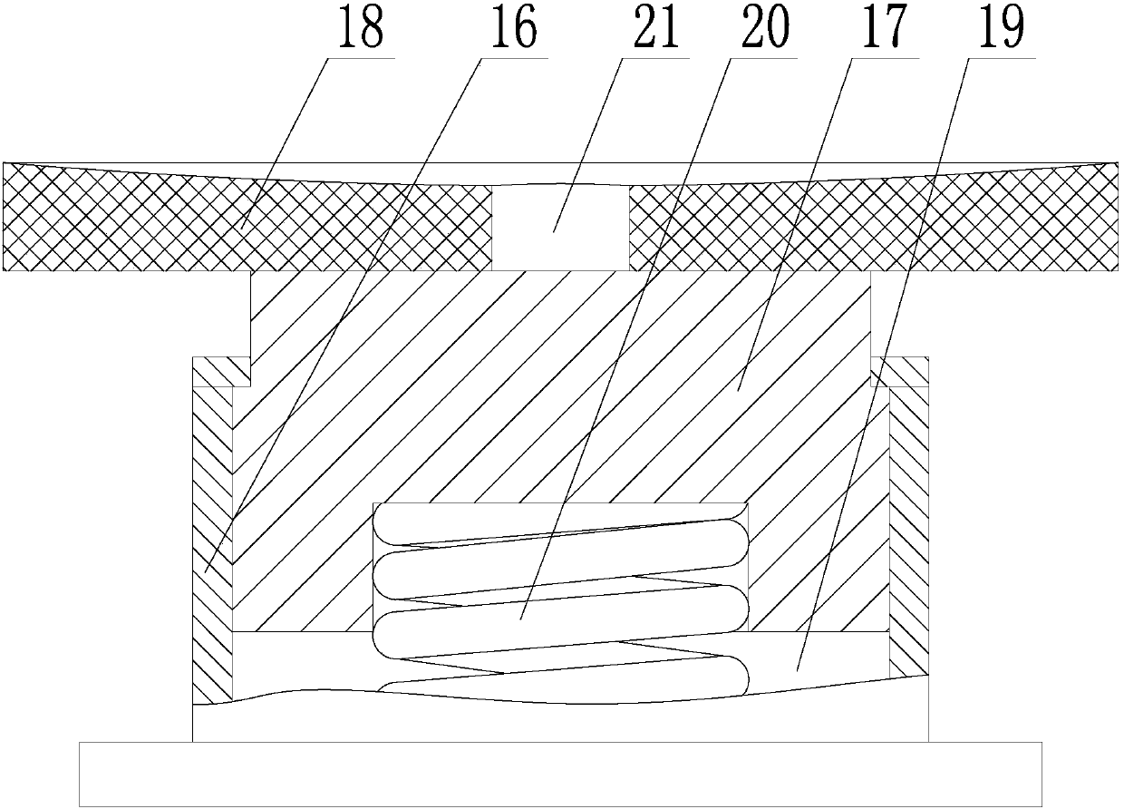
[0038] Such as Figure 1~3 As shown, an auxiliary support device for processing large thin-walled components, including a base 1, an X-direction position adjustment unit, a Y-direction position adjustment unit, and a Z-direction position adjustment unit;

[0039] The X-direction position adjustment unit includes an X-direction rail 2, an X-direction slider 3, an X-direction platform 4, an X-direction screw rod 5, an X-direction nut 6 and an X-direction drive motor 7; the X-direction rail 2 is horizontally fixed Installed on the upper surface of the base 1, there are two X-guiding rails 2 distributed in parallel; the X-direction slider 3 is arranged on the X-guiding rail 2, and the X-direction slider 3 and the X-guiding rail 2 are horizontally slidable; The platform 4 is fixedly installed on the X-direction slider 3, the X-direction s...


PUM


Abstract

The invention discloses an auxiliary supporting device for processing large thin-wall components and a using method for the auxiliary supporting device. The device comprises a base, an X-direction position regulating unit, a Y-direction position regulating unit and a Z-direction position regulating unit. The using method for the device comprises the following steps of: integrally putting the auxiliary supporting device onto a workbench of a processing machine tool; controlling an electric lifting post to descend, and ensuring a supporting plate to be positioned below a Y-direction platform; putting thin-wall components onto the upper surface of the Y-direction platform, and enabling drilled positions of the thin-wall components to be roughly aligned to the supporting plate; separately controlling an X-direction drive motor and a Y-direction drive motor to rotate to drive an X-direction platform and the Y-direction platform to horizontally move, enabling the drilled positions of the thin-wall components to be fine aligned to the supporting plate, and ensuring the center lines of to-be-processed holes in the thin-wall components to be superposed with the center line of a positioning hole in the supporting plate; positioning and clamping the thin-wall components onto the workbench of the processing machine tool; controlling the electric lifting post to ascend, and ensuring the upper surface of the supporting plate to be in tight fit to the thin-wall components; and starting the processing machine tool to start drilling processing.

Description

technical field [0001] The invention belongs to the technical field of aerospace parts processing, and in particular relates to an auxiliary supporting device for processing large thin-walled components and a use method thereof. Background technique [0002] In the field of aerospace, there are a large number of metal or non-metallic large thin-walled components. Limited by their thin-walled structures, large thin-walled components generally have the disadvantage of low stiffness. During the processing of large thin-walled components , must be affected by the cutting force, and the machining deformation and chattering phenomenon will occur under the action of the cutting force. [0003] At present, the use of large non-metallic thin-walled components is increasing day by day, and the rigidity of non-metallic large thin-walled components is lower than that of metal components, and their processing deformation and chattering are more serious. [0004] In the field of aerospac...

Claims


Application Information

Patent Timeline
Patent Type & Authority Patents(China)
IPC IPC(8): B26D7/14
CPCB26D7/14
Inventor 王奔郑耀辉王明海李晓鹏马书娟
Owner SHENYANG AEROSPACE UNIVERSITY
Learn More