Injection molded retention method for power transfer devices

A retainer, on-site molding technology, applied in the direction of transmission, transmission parts, differential transmission, etc.

Active Publication Date: 2017-02-15
MAGNA POWERTRAIN USA
View PDF5 Cites 2 Cited by
  • Summary
  • Abstract
  • Description
  • Claims
  • Application Information

AI Technical Summary

Problems solved by technology

Known disadvantages associated with such "bolt-on" multi-piece axle housing assemblies include the expense associated with machining the threaded holes, the need for sealing flanges, and the precise torque requirements of the threaded fasteners

Method used


Image

  • Injection molded retention method for power transfer devices
  • Injection molded retention method for power transfer devices
  • Injection molded retention method for power transfer devices

Examples


Embodiment Construction

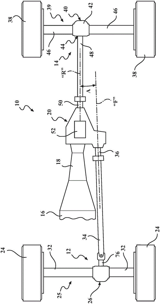
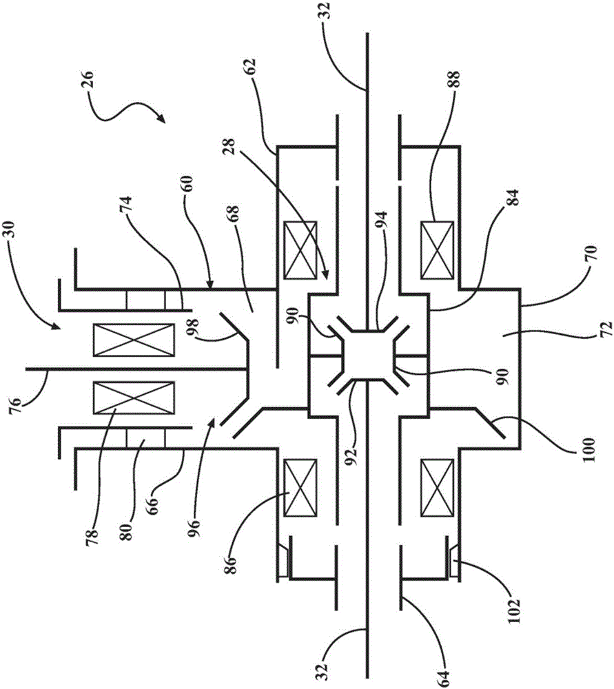
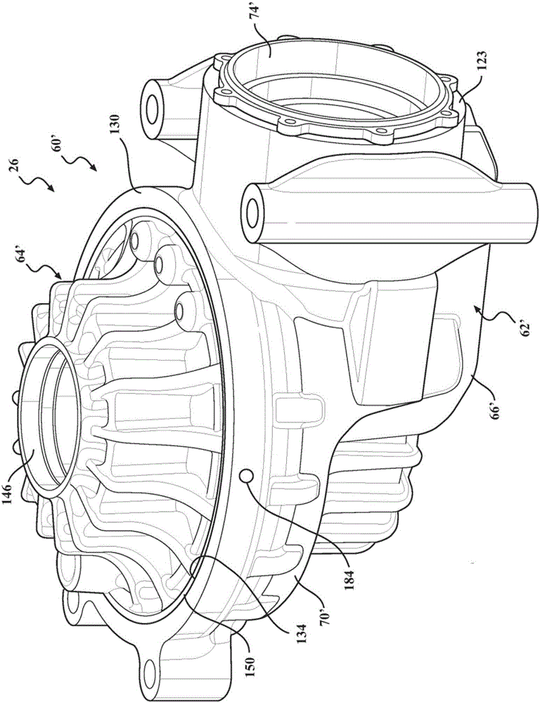
[0024] One or more exemplary embodiments of a power transmission device will now be described more fully with reference to the accompanying drawings. The power transmission device, in particular the drive axle unit, is suitable for use in a motor vehicle driveline / drivetrain application for transmitting drive torque from an input to at least one output through a gear set. However, exemplary embodiments are provided only so that this disclosure will be thorough, and will fully convey the intended scope to those skilled in the art. Numerous specific details are set forth such as, for example, components, devices, assemblies and methods in order to provide a thorough understanding of various embodiments of the present disclosure.

[0025]The terminology used herein is for describing particular exemplary embodiments only and is not intended to be limiting. As used herein, the singular forms "a", "an" and "the" may be intended to include the plural forms as well, unless the contex...


PUM


Abstract

A drive axle unit for use in a motor vehicle having a multi-piece axle housing assembly including at least two housing components interconnected via at least one in-situ molded retainer component. A method for securing at least two housing components of an axle housing assembly by injecting a molten material into a pair of aligned mold indentations formed in the two housing components which solidifies to create an in-situ molded retainer component.

Description

[0001] Cross References to Related Applications [0002] This application claims priority to U.S. Patent Application Serial No. 15 / 213,452, filed July 19, 2016, entitled "INJECTION MOLDED RETENTION METHOD FOR POWER TRANSFER DEVICES" right, which claims U.S. Provisional Patent Application Serial No. 62 / 197,996, filed July 28, 2015 and titled "INJECTION MOLDED RETENTION METHOD FOR POWER TRANSFER DEVICES" rights and priorities. The entire disclosure of each of the above applications is incorporated herein by reference. technical field [0003] The present disclosure generally relates to power transfer devices of the type used in motor vehicle drivelines. More specifically, the present disclosure relates to axle drive units having a multi-piece housing assembly having at least two housing components that use injection molded retainers to interconnected, and the injection molding process is operable to manufacture a mold-in-place retainer positioned for interconnecting at least ...

Claims


Application Information

Patent Timeline
IPC IPC(8): B29C45/14B29C45/26F16H57/032B29K71/00B29L31/30
CPCB29C45/14467B29C45/2602F16H57/032B29L2031/30B29K2071/00F16H2057/0325F16H48/38F16H57/037F16H48/08
Inventor 保罗·W·施瓦克布雷德利·S·凯琴尔
Owner MAGNA POWERTRAIN USA
Why Eureka
Try Eureka