

Optical lens collecting mechanism
A technology of reclaiming mechanism and optical lens, applied in the direction of conveyor objects, transportation and packaging, etc., can solve the problems of trouble in taking, damage, friction of lenses, etc., and achieve the effect of convenient reclaiming, good effect and quality assurance.
- Summary
- Abstract
- Description
- Claims
- Application Information
AI Technical Summary
Problems solved by technology
Method used
Image

Examples
Embodiment Construction
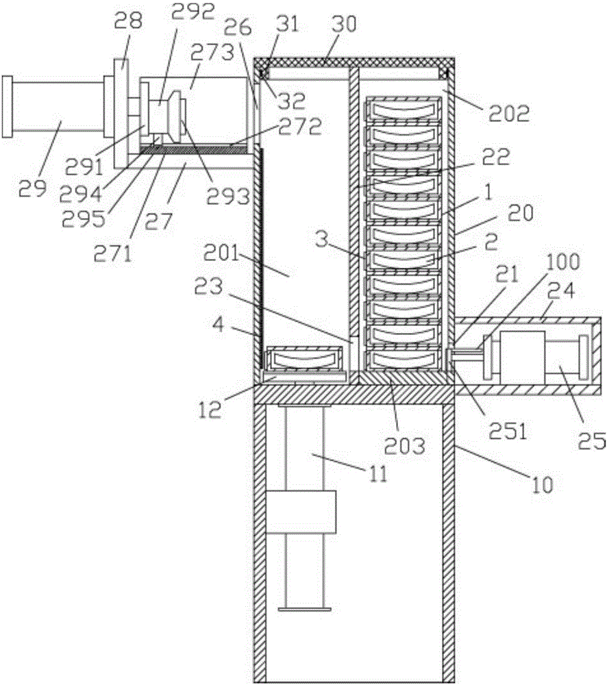
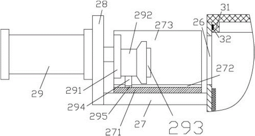
[0020] Examples, see e.g. Figure 1 to Figure 2 As shown, a kind of optical lens retrieving mechanism comprises frame 10, and the top plate of described frame 10 is fixed with upper placement box body 20, and the bottom of the right side plate of upper placement box body 20 has pushing material through hole 21, The middle part of the upper casing 20 is fixed with a dividing plate 22, the bottom of the dividing plate 22 has an intermediate through hole 23 aligned with the pushing hole 21, and the upper placing casing 20 on the left side of the dividing plate 22 has a Feeding cavity 201, the upper placement box body 20 on the right side of the partition plate 22 has a discharge cavity 202, and a plurality of lens boxes 1 stacked up and down are stacked in the discharge cavity 202, and in the lens box 1 Eyeglasses 2 are placed, and the bottom right side of casing 20 is fixed with pushing material cylinder placement box 24, is fixed with pushing material cylinder 25 in the materia...
PUM
 Abstract
Description
Claims
Application Information