Separation and recovery apparatus for waste paper and plastic composite material, and method thereof

A composite material, separation and recycling technology, applied in the field of waste paper-plastic composite material separation and recycling devices, can solve the problems of increased recycling cost, high cost, large water consumption, etc., and achieves easy recycling and sorting, easy separation and recycling, water and energy consumption. small effect

Inactive Publication Date: 2012-02-22
曾涛
View PDF4 Cites 11 Cited by
  • Summary
  • Abstract
  • Description
  • Claims
  • Application Information

AI Technical Summary

Problems solved by technology

[0005] The existing above-mentioned physical method has the following disadvantages: 1. The fragments must be rolled at high speed under the impact of high-speed water to make the paper layer and plastic layer glass, so the energy consumption is large. High water consumption, 2. The volume of the drum must be small enough to allow the debris to roll at high speed, which restricts the production efficiency and output of separation and recovery; 3. Because the debris is too small, each piece of debris appears light, and each piece roughly follows the The water flow around it moves synchronously. This synchronous movement is not conducive to the formation of rubbing effect, so it is not conducive to making the paper layer separate from the plastic base layer; After being separated from plastic fragments, they are still mixed together, and certain process steps are required to separate the two according to categories, which undoubtedly increases the cost of recycling
In short, the separation and recovery effect of the existing physical method is half the effort, the cost is high, and sometimes the gain outweighs the gain

Method used


Image

  • Separation and recovery apparatus for waste paper and plastic composite material, and method thereof
  • Separation and recovery apparatus for waste paper and plastic composite material, and method thereof
  • Separation and recovery apparatus for waste paper and plastic composite material, and method thereof

Examples


Embodiment 1

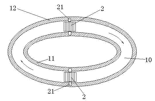
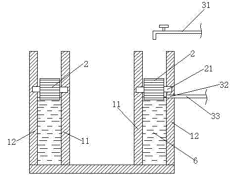
[0028] figure 1 , figure 2 , Figure 5 As shown, the waste paper-plastic composite material separation and recovery device includes an annular water tank, and its cavity 10 is annular. The annular water tank has an annular inner side wall 11 and an annular outer side wall 12. The annular water tank is equipped with two rollers 2, and the rotating shaft of each roller 21. The installation direction is the horizontal direction, and the surface of each roller is provided with convex teeth 22, and each roller is connected with a motor that drives it to rotate. The two ends of each roller shaft 21 are erected respectively on the annular inner wall 11 and the annular outer wall 12 of the water tank, that is, the two ends of each roller shaft are respectively erected on both sides of the tank cavity 10; the annular water tank is provided with a water supply pipe 31 and a slurry discharge The port 32 is connected with a slurry discharge pipe 33 to the slurry discharge port 32. Th...

Embodiment 2

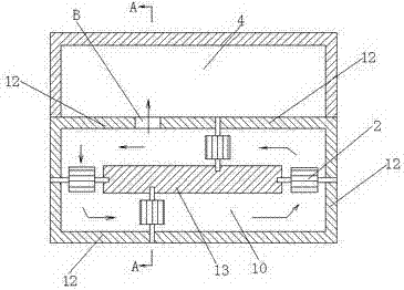
[0031] image 3 , Figure 4 , Figure 5 As shown, in this embodiment, the tank cavity of the annular water tank is annular, and the center of the water tank is an inner wall 13, and the surrounding sides of the inner wall form the inner surface of the annular water tank, and four rollers 2 are installed in the annular water tank. The two ends of each roller rotating shaft are erected on the tank inner wall 13 and the annular outer side wall 12 respectively. The slurry outlet of the annular water tank is the lowest point of the annular outer wall 12 elevation ( image 3 , Figure 4 The part indicated by B in the middle), so Figure 3, Figure 4 The part indicated by middle B forms a pulp outlet, and a pulp pool 4 is arranged next to the pulp outlet. When the height of the tank cavity water surface exceeds that shown in Figure 3, Figure 4 At the position indicated by middle B, the paper residue pulp naturally overflows and enters the CIMC stock tank 4. In order to prevent...

Embodiment 3

[0033] In the third embodiment, three pulp outlets are set at the same time, and the vertical elevations of each pulp outlet are different, wherein the vertical position of the uppermost pulp outlet is slightly lower than the vertical position of the roller shaft, and the bottom row The vertical position of the slurry port is located at the lower part of the annular outer wall, and the vertical position of the middle slurry discharge port is located at the middle part of the annular outer wall. In this way, different pulp outlets can be opened according to different shredded paper, for example, when the shredded paper is deposited in the water, the lower pulp outlet can be opened to facilitate the shredded paper to be discharged from the annular water tank; When the water tends to float upward, the upper pulp discharge port can be opened to facilitate the discharge of shredded paper residue into the annular water tank.


PUM


Abstract

The invention relates to a separation and recovery apparatus for a waste paper and plastic composite material. The apparatus comprises a circular water tank. The circular water tank is provided with a plurality of rollers. A rotation shaft installation direction of each roller is a horizontal direction. Both ends of the rotation shaft of each roller are respectively erected on both sides of the tank chamber. The surface of each roller is provided with convex teeth. The rollers are connected with a motor, wherein the motor drives the rollers to rotate. The invention further discloses a separation and recovery method for the waste paper and plastic composite material. The apparatus and the method of the present invention have the following advantages that: the cost is low, the energy consumption is low, the separation effect of the paper layer and the plastic layer is good, and the recovery is easily performed.

Description

[0001] Technical field: [0002] The invention belongs to the technical field of waste separation and recycling, and in particular relates to a waste paper-plastic composite material separation and recycling device and method. Background technique [0003] Paper-plastic composite materials, especially paper-plastic composite woven bags, have the advantages of waterproof, high temperature resistance, wear resistance and high toughness. , and its consumption is huge. Most of the paper-plastic composite materials can float on the water surface after soaking in water. The base layer of most paper-plastic composite materials is a plastic base layer and the surface layer is a paper layer. Paper-plastic composite materials are difficult to recycle after use, mainly because the plastic base layer and the paper layer are tightly bonded and difficult to separate. Therefore, a large number of used paper-plastic composite woven bags are abandoned and not recycled every day. waste, an...

Claims


Application Information

Patent Timeline
Patent Type & Authority Applications(China)
IPC IPC(8): B09B3/00B29B17/02
CPCY02W30/62
Inventor 柯伟文
Owner 曾涛
Why Eureka
Try Eureka