Floor heating floor

A floor and floor heating technology, applied in the field of floor heating, can solve the problem of no decorative parts on the floor, and achieve the effect of increasing heat dissipation and good decoration effect

Inactive Publication Date: 2017-02-15
SUZHOU HENGDAL IND MATERIALS CO LTD
View PDF8 Cites 1 Cited by
  • Summary
  • Abstract
  • Description
  • Claims
  • Application Information

AI Technical Summary

Problems solved by technology

In addition, the current floor usually has no decorative parts. If decorative parts are added to the floor, the decorative effect can be added

Method used


Image

  • Floor heating floor
  • Floor heating floor

Examples


Embodiment Construction

[0017] The present invention will be further described below in conjunction with the accompanying drawings. The following examples are only used to illustrate the technical solution of the present invention more clearly, but not to limit the protection scope of the present invention.

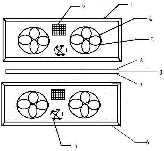
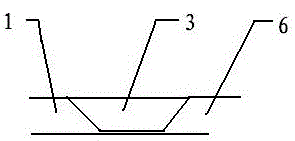
[0018] Such as figure 1 and figure 2 As shown, a ground heating floor includes a board body, a heat dissipation device is arranged in the board body, and decorative parts are arranged around the heat dissipation device, and the board body (the first floor 1 and the second floor 6) is connected by a connecting block 3 In order to be bonded together, the connecting block 3 includes a surface A and a surface B, which are engaged and bonded with two floor panels (the first floor panel 1 and the second floor panel 6 ) respectively.

[0019] Preferably, the heat dissipation device includes a micro fan 7 and a heat dissipation hole 2, the micro fan 7 is connected to a power supply through wires, and...


PUM


Abstract

The invention discloses a floor heating floor. The floor heating floor comprises floor bodies. Heat dissipation devices are arranged in the floor bodies. Decoration pieces are arranged around the heat dissipation devices. The floor bodies are bonded through a connecting block. The connecting block comprises a face A and a face B which are clamped and bonded to the two floor bodies correspondingly. According to the floor heating floor, the heat dissipation devices are arranged, mini-type fans are arranged in the floor, heat dissipation holes are formed in the floor, and therefore the heat dissipation effect is improved. The floor is provided with the decoration pieces, and a good decoration effect can be achieved.

Description

technical field [0001] The invention relates to a floor heating floor, which belongs to the field of home decoration building materials. Background technique [0002] The current floor heating technology usually buries heat conduction pipes under the floor. If the heat cannot be dissipated in time, the accumulated heat will damage the floor. In addition, the current floor usually has no decorative parts. If decorative parts are added to the floor, the decorative effect can be added. Contents of the invention [0003] The technical problem to be solved by the present invention is to overcome the defects of the prior art and provide a floor heating floor, which has a good heat dissipation effect and is equipped with decorative parts to achieve a good decoration effect. [0004] In order to solve the above technical problems, the present invention provides a floor heating floor, which is characterized in that it includes a board body, a heat dissipation device is arranged in...

Claims


Application Information

Patent Timeline
Patent Type & Authority Applications(China)
IPC IPC(8): E04F15/02
CPCE04F15/02E04F2290/023
Inventor 徐志明
Owner SUZHOU HENGDAL IND MATERIALS CO LTD
Why Eureka
Try Eureka