Probe assembly suitable for strong-shearing unsteady flow test of aeroengine

A probe and component technology, applied in the field of testing, can solve the problems of strong three-dimensional and strong shear testing to be improved, and achieve the effect of high temporal and spatial resolution

Active Publication Date: 2017-02-15
INST OF ENGINEERING THERMOPHYSICS - CHINESE ACAD OF SCI
View PDF5 Cites 20 Cited by
  • Summary
  • Abstract
  • Description
  • Claims
  • Application Information

AI Technical Summary

Problems solved by technology

Foreign aero-engine companies such as British RR Company, American PW Company, and GE Company have developed various forms of steady-state and dynamic test technologies, obtained a large amount of test data, and laid an important technical foundation for the improvement of the test system and design system. However, the test for the strong three-dimensional, strong shear and strong unsteady flow field inside the aero-engine still needs to be improved
At present, there are few systematic studies on the basis of testing technology in China, and there is a lack of research on advanced testing methods for the internal flow of the complete engine and components, which is far from meeting the needs of my country's civil aviation engine development. The test technology and method of the internal flow test of the engine has become a key issue in the field of high performance aviation gas turbine engine test technology

Method used


Image

  • Probe assembly suitable for strong-shearing unsteady flow test of aeroengine
  • Probe assembly suitable for strong-shearing unsteady flow test of aeroengine
  • Probe assembly suitable for strong-shearing unsteady flow test of aeroengine

Examples


Embodiment Construction

[0027] Exemplary embodiments of the present invention will be described in detail below with reference to the accompanying drawings, wherein the same or similar reference numerals represent the same or similar elements. In addition, in the following detailed description, for purposes of explanation, numerous specific details are set forth in order to provide a comprehensive understanding of the embodiments of the present disclosure. It may be evident, however, that one or more embodiments may be practiced without these specific details. In other instances, well-known structures and devices are shown in diagrammatic form to simplify the drawings.

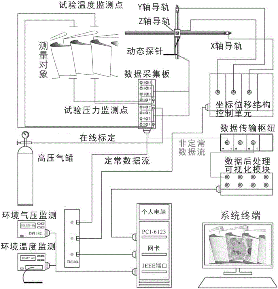
[0028] According to the general inventive concept of the present invention, a test system is proposed, the test system includes a measurement module and a central control module, wherein the measurement module is configured to be able to perform static measurement and dynamic measurement.

[0029] According to a preferred embodiment...


PUM


Abstract

The invention discloses a probe assembly suitable for a strong-shearing unsteady flow test of an aeroengine and provides the probe assembly (1). The probe assembly (1) comprises a conjunction box (2) and a probe rod portion (3) in the shape of an elongated rod, wherein the probe rod portion (3) is configured to be inserted into the conjunction box (2). The probe rod portion (3) comprises a first section (31), a second section (32) and a third section (33) whose diameters are successively decreased in a stepwise manner, wherein the third section (33) is provided with a sensing portion (34) disposed at the end portion of the probe rod portion (3), the sensing portion (34) is in the shape of an index finger and comprises a cylindrical surface (341) and an end portion curved surface (342), the cylindrical surface (341) and the end portion curved surface (342) are each provided with a measurement hole (343), and pressure sensors (4) are respectively arranged at positions, which are disposed at the inner-side wall of the hollow-tubular-shaped tube wall of the probe rod portion (3), at the two measurement holes (343). The probe assembly has high precision and high time-space resolution.

Description

technical field [0001] The invention relates to the technical field of testing, in particular to the testing technology of an aviation gas turbine engine, in particular to a probe assembly with high precision and high temporal and spatial resolution. Background technique [0002] Extremely demanding requirements such as high load, high efficiency, high reliability, and long life of aero-engines pose great challenges to the design technology of the engine's compression system, expansion system, and intake and exhaust system. Due to the effects of high-speed rotation, blade surface curvature, and gas viscosity, the flow inside the aeroengine blade channel is very complex, which is a typical strong three-dimensional, strong shear, strong unsteady turbulent flow, and there are various complex vortex flows. The secondary flow expressed in the form of the system, etc. In the development of high-performance aeroengines, it is urgent to clearly understand the internal flow details ...

Claims


Application Information

Patent Timeline
Patent Type & Authority Applications(China)
IPC IPC(8): G01M15/02
CPCG01M15/02
Inventor 张燕峰卢新根朱俊强韩戈韩建涛阳诚武
Owner INST OF ENGINEERING THERMOPHYSICS - CHINESE ACAD OF SCI
Why Eureka
Try Eureka