Laser detecting device for concealed flying object

A flying target, laser detection technology, applied in the field of invisible flying targets, can solve the problems of poor resistance to electronic interference, limited detection ability, low range resolution, etc., to achieve sensitive response, high detection efficiency, high spatial and temporal resolution. Effect

Inactive Publication Date: 2006-09-06
SHANGHAI INST OF OPTICS & FINE MECHANICS CHINESE ACAD OF SCI
View PDF0 Cites 11 Cited by
  • Summary
  • Abstract
  • Description
  • Claims
  • Application Information

AI Technical Summary

Problems solved by technology

Therefore, using microwave radar to detect invisible flying targets has limited detection capability, low range resolution, and poor resistance to electronic interference.

Method used


Image

  • Laser detecting device for concealed flying object
  • Laser detecting device for concealed flying object
  • Laser detecting device for concealed flying object

Examples


Embodiment Construction

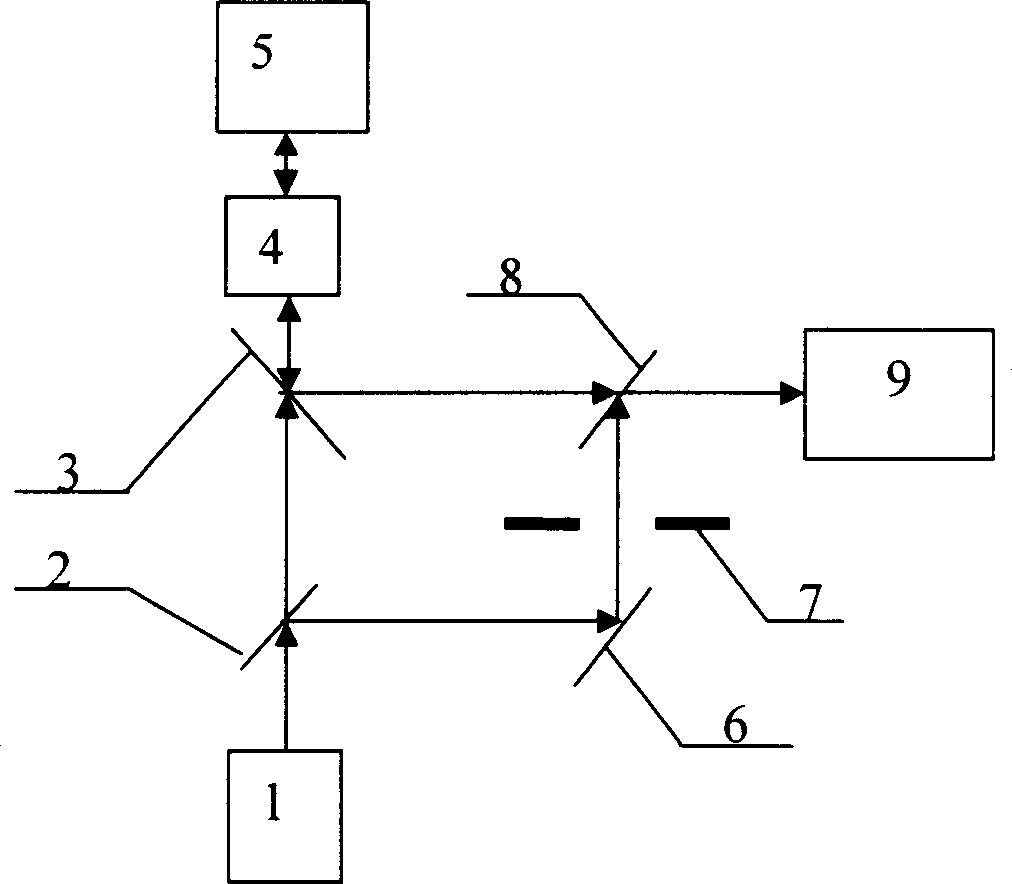
[0035] see first figure 1 , figure 1 It is a block diagram of the overall structure of the laser detection device for the invisible flying target of the present invention. As can be seen from the figure, the laser detection device for the invisible flying target of the present invention consists of a laser 1, a first beam splitter 2, a second beam splitter 8, and a polarizing beam splitter 3 , 1 / 4 wave plate 4, telescope 5, total reflection mirror 6, switch 7 and optical Doppler imaging detection device 9, and its positional relationship is: on the optical axis of the output beam of the laser 1, set in sequence There is a first beam splitter 2, a polarization beam splitter 3, a 1 / 4 wave plate 4 and a telescope 5, and the first beam splitter 2 and the polarization beam splitter 3 are all set at 45° with the output light beam. The reflected beam direction of the first beam splitter 2 is equipped with a total reflection mirror 6, and the reflected light of the total reflection m...


PUM


Abstract

The device comprises: a laser, a first / second spectroscope, a polarization beam-splitter piece, a 1 / 4 wave plate, a telescope, a full-reflection mirror on reflection beam of the first spectroscope, a switch, and an optical Doppler imaging detector on the output light direction of second spectroscope. Wherein, arranging the first spectroscope and beam-splitter piece both as 45Deg, 1 / 4 wave plate and telescope on the OA of output beam of the laser in turn; arranging with 45Deg the second spectroscope on the cross point of switch light path and reflection light path of laser echo of beam-slitter piece. This invention can determine the position, height, velocity and direction.

Description

technical field [0001] The invention relates to a colorless flying target, in particular to a laser detection device for a colorless flying target using high-resolution laser Doppler imaging technology to obtain speed, height and direction information of the colorless flying target. Background technique [0002] The monitoring and detection of invisible flying targets plays an important role in the fields of experimentation and safety. At present, the opaque absorbing coatings and structures used in opaque flying targets are mainly aimed at centimeter waves, but have limited ability to infrared and visible light, especially the near-ultraviolet opaque technology is more difficult. Therefore, the use of microwave radar to detect invisible flying targets has limited detection capabilities, low range resolution, and poor resistance to electronic interference. [0003] The detection technology based on high-resolution laser Doppler imaging can scan the atmosphere in real time a...

Claims


Application Information

Patent Timeline
Patent Type & Authority Applications(China)
IPC IPC(8): G01S17/50G01S17/58
Inventor 刘继桥陈卫标卜令兵周军余婷
Owner SHANGHAI INST OF OPTICS & FINE MECHANICS CHINESE ACAD OF SCI
Why Eureka
Try Eureka