Antenna calibration tool

An antenna calibration and tool technology, applied in receiver monitoring, transmitter monitoring and other directions, can solve the problems of inability to accurately judge the antenna radiation orientation, long-term influence on radiation circuit indicators, and increase the cost of network deployment, so as to reduce the difficulty of survey and facilitate repetition. The effect of using and avoiding the hidden danger of the antenna

Active Publication Date: 2017-02-15
COMBA TELECOM TECH (GUANGZHOU) CO LTD +2
View PDF7 Cites 0 Cited by
  • Summary
  • Abstract
  • Description
  • Claims
  • Application Information

AI Technical Summary

Problems solved by technology

[0002] In the current antenna application, there are two common methods for the positioning of the antenna installation site and the radiation direction. One is to manually mark the coordinates and radiation direction of the antenna on the electronic map through on-site survey, which is difficult to identify and cannot accurately determine the radiation direction of the antenna, etc. Various indicators, in the optimization and layout of the communication network, lead to problems such as the ne

Method used


Image

  • Antenna calibration tool
  • Antenna calibration tool
  • Antenna calibration tool

Examples


Example Embodiment

[0029] The embodiments of the present invention will be described in detail below in conjunction with the drawings:

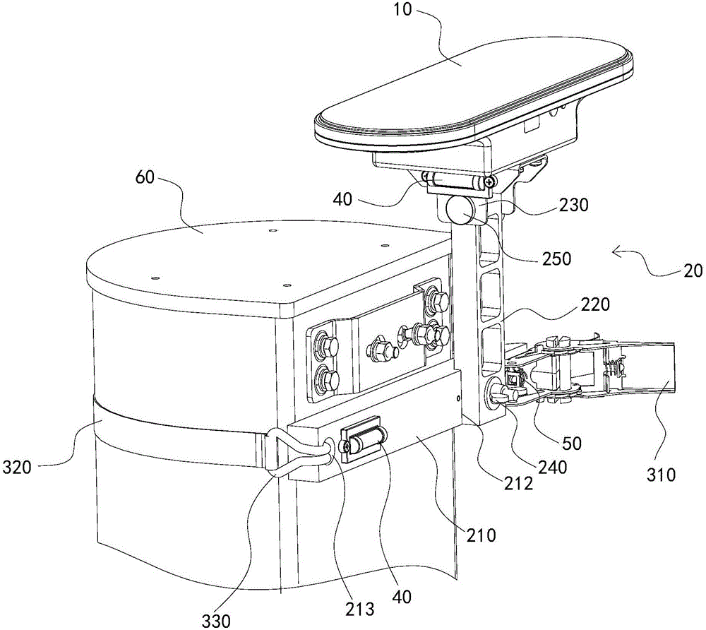
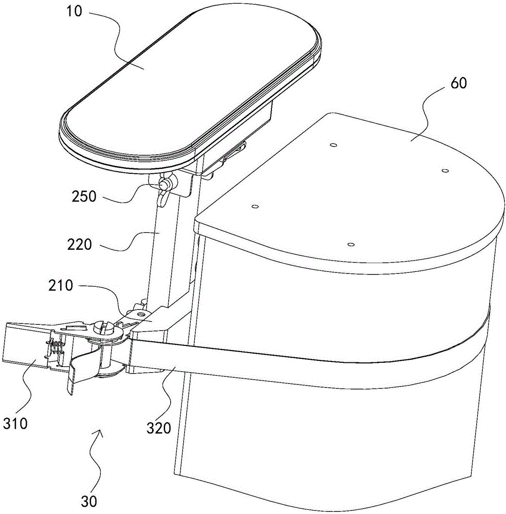
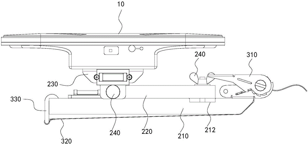
[0030] Such as Figure 1 to Figure 3 As shown, an antenna calibration tool includes an antenna sensing module 10, a mounting frame assembly 20 for driving the antenna sensing module 10 to rotate, and a binding assembly 30 for binding the mounting frame assembly 20 to an antenna 60. The antenna sensing The module 10 can rotate around the first direction and the second direction, and the first direction and the second direction are arranged at an angle.

[0031] The antenna calibration tool can quickly fix the antenna sensing module 10 on the antenna 60 by bundling the components 30, which is easy to install, without the antenna sensing module 10 being built into the antenna 60, which is easy to reuse, has good flexibility, and has strong adaptability. Function Purchase antennas in large quantities or rectify existing antennas to reduce network layout and optimize cos...


PUM


Abstract

The invention relates to an antenna calibration tool. The antenna calibration tool comprises an antenna induction module, a mounting rack assembly which drives the antenna induction module to rotate and a binding assembly which binds the mounting rack assembly onto an antenna; and the antenna induction module can rotate along first and second directions, and an included angle is formed between the first and second directions. According to the antenna calibration tool, the antenna induction module can be fixed on the antenna rapidly via the binding assembly, installation is convenient, it is not required to mount the antenna in the antenna induction module, the tool can be used repeatedly, the flexibility is high, and the network layout and optimization cost is reduced; and the antenna calibration tool senses indexes including the radiation direction, the geographic position and lower inclination angle via the antenna induction module, the antenna induction module can rotate around the first and second directions according to practical requirements to adjust the position relative to the antenna, rapid sensing is realized, and compared with manual antenna identification, the precision is improved greatly, the exploration difficulty is decreased greatly, and resource configuration is activated.

Description

technical field [0001] The invention relates to the technical field of antenna calibration, in particular to an antenna calibration tool. Background technique [0002] In the current antenna application, there are two common methods for the positioning of the antenna installation site and the radiation direction. One is to manually mark the coordinates and radiation direction of the antenna on the electronic map through on-site survey, which is difficult to identify and cannot accurately determine the radiation direction of the antenna, etc. Various indicators, in the optimization and layout of the communication network, lead to problems such as too dense or too weak a network, resulting in uneven resource allocation and waste. The other is that the electronic sensing device is built into the antenna, which results in high cost of the antenna, and the old antenna products need to be modified simultaneously, which increases the cost of network deployment. On the other hand, ...

Claims


Application Information

Patent Timeline
IPC IPC(8): H04B17/12H04B17/21
CPCH04B17/12H04B17/21
Inventor 黄潮生周浩赖军茂马泽峰游建军段红彬
Owner COMBA TELECOM TECH (GUANGZHOU) CO LTD
Why Eureka
Try Eureka