
Method for implementing SCell control, terminal and network side

A secondary cell and network-side technology, applied in the direction of network traffic/resource management, advanced technology, climate sustainability, etc., can solve problems such as waste of carrier resources, inability to activate or deactivate SCell, and inability to determine the signal quality status of a cell , to achieve the effect of reducing terminal power consumption and improving spectrum resource utilization

Inactive Publication Date: 2017-02-15
ZTE CORP
View PDF5 Cites 5 Cited by
  • Summary
  • Abstract
  • Description
  • Claims
  • Application Information

AI Technical Summary

Problems solved by technology

However, users cannot perceive the existence of carrier aggregation. When activating or deactivating SCells on the network side, although users experience the speed of data transmission, they cannot determine the signal quality status of the cell, nor can they activate or deactivate SCells. It is easy to cause waste of carrier resources

Method used


Image

  • Method for implementing SCell control, terminal and network side
  • Method for implementing SCell control, terminal and network side
  • Method for implementing SCell control, terminal and network side

Examples


Embodiment 1

[0113] The terminal in this embodiment is a terminal supporting carrier aggregation. Figure 5 It is the method flowchart of the first embodiment of the present invention, as Figure 5 shown, including:

[0114] Step 500, the terminal displays signal quality parameters of one or more secondary cells; in this step, the signal quality parameters are obtained by the terminal itself through detection of system parameters of the accessed network. specific,

[0115] The signal quality parameter can display the signal quality strength of the secondary cell through the status bar at the top of the terminal screen. In the prior art, the display of the mobile network signal belongs to the display of the signal quality and strength of the primary cell. Considering that there may be multiple secondary cells, the status bar can only display the signal quality parameters of the strongest secondary cell, and the signal quality parameters of all secondary cells can be queried and displayed...

Embodiment 2

[0120] In this embodiment, the terminal side is used as a main body to describe the present invention. Figure 6 It is the method flowchart of the second embodiment of the present invention, as Figure 6 shown, including:

[0121] Step 600: Determine that the signal quality of the secondary cell is poor through the signal quality parameters of the secondary cell displayed by the terminal, or determine that the resource occupancy rate of the terminal service is less than the first threshold, and input an instruction to select and determine some of the secondary cells to be deactivated;

[0122] The selected and determined secondary cells are deactivated by selecting an activation and deactivation switch added at the position where the signal quality parameter of each secondary cell is displayed.

[0123] Step 601, the terminal expands information elements in the event test report sent to the network side, adds processing messages for deactivating selected and determined partia...


PUM


Abstract

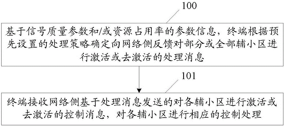
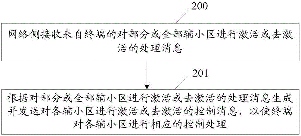
The invention discloses a method for implementing SCell control, a terminal and a network side. The method comprises the steps that based on signal quality parameters and / or parameter information of a resource occupancy rate, the terminal determines to feed processing information of activating or deactivating some or all SCells back to the network side according to a pre-set processing strategy; and the terminal receives control information of activating or deactivating all the SCells that is transmitted by the network side based on the processing information. The method of the invention improves the utilization rate of spectrum resources and reduces the terminal power consumption by feeding the processing of activating or deactivating some or all the SCells back to the network side.

Description

technical field [0001] The present invention relates to long-term evolution technology, in particular to a method for realizing secondary cell control, a terminal and a network side. Background technique [0002] Currently, leading long-term evolution (LTE) operators are actively deploying carrier aggregation, and use spectrum resources in their hands as much as possible. The carrier aggregation system consists of at least one primary cell (PCell) and multiple secondary cells (SCell); among them, PCell is used to transmit signals and data, SCell is used to transmit data, and the network side adds or releases RRC layer signaling, and The carrier frequency resources are activated or deactivated by the MAC to control the frequency spectrum resources of the carrier aggregation, thereby increasing the peak rate of data transmission. [0003] The SCell activation or deactivation mechanism introduced in the carrier aggregation system, the network side (evolved Node B (eNodeB)) dyn...

Claims


Application Information

Patent Timeline
IPC IPC(8): H04W24/02H04W52/02
CPCH04W24/02H04W52/0212H04W28/18Y02D30/70
Inventor 白丽
Owner ZTE CORP
Learn More