Boosting and assisted unplugging locking device and cabinet device by using the same

A locking device and boosting technology, which can be applied in the direction of cabinet/box/drawer parts, electrical equipment shell/cabinet/drawer, electrical components, etc., can solve the problems of heavy weight, large volume and limited use range , to achieve the effect of simple structure and small volume

Active Publication Date: 2017-02-15
CHINA AVIATION OPTICAL-ELECTRICAL TECH CO LTD
View PDF5 Cites 2 Cited by
  • Summary
  • Abstract
  • Description
  • Claims
  • Application Information

AI Technical Summary

Problems solved by technology

Although this kind of locking device has the function of pushing and pulling out, it is bulky, heavy, and has many supporting parts. Usually, it needs to be used in pairs, and requires a certain installation and operation space. Therefore, its scope of use It is often restricted. In addition, the handle 6 will generate pressure and tension on the front panel of the chassis 1 during use. For the chassis that cannot bear the force on the front panel, this locking device is very inappropriate.

Method used


Image

  • Boosting and assisted unplugging locking device and cabinet device by using the same
  • Boosting and assisted unplugging locking device and cabinet device by using the same
  • Boosting and assisted unplugging locking device and cabinet device by using the same

Examples


Embodiment Construction

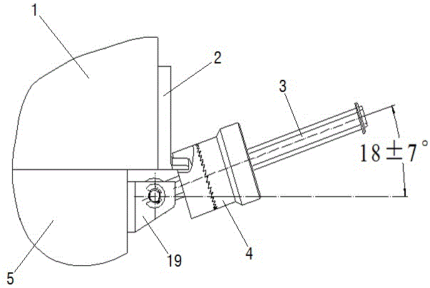
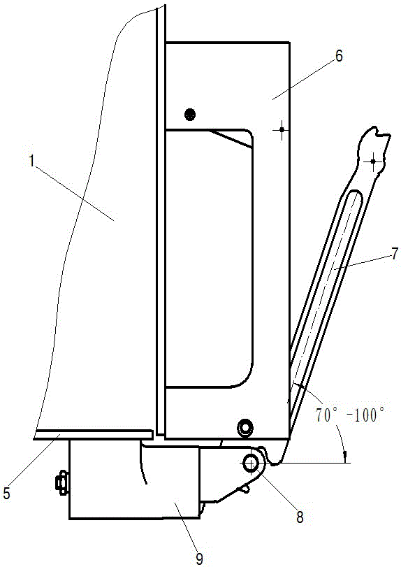
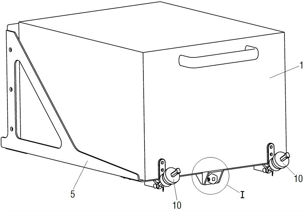
[0026] An example of a chassis device such as Figure 3~Figure 7 As shown, it includes a chassis 1, a bracket 5, and a push-and-pull locking device arranged on the chassis 1 and the bracket 5. The boost-assisted and pulled-out locking device includes a threaded seat 11 fixed on the front end of the bottom of the bracket 5 and a fixed The supporting base 12 at the front end of the bottom of the cabinet 1. The threaded seat 11 includes a threaded seat horizontal plate and a threaded seat vertical plate perpendicular to each other. The threaded seat horizontal plate is provided with a fixing hole for being fixedly connected with the bracket 5. The support seat 12 also includes a mutually perpendicular support seat horizontal plate and a support seat. The vertical plate and the horizontal plate of the support seat are provided with fixing holes for being fixedly connected with the chassis 1 .

[0027] A threaded hole 20 with an axis extending in the front-to-back direction is pro...


PUM


Abstract

The present invention provides a boosting and assisted unplugging locking device and a cabinet device by using the same. The boosting and assisted unplugging locking device includes a screw thread seat fixed on a bracket and a support seat fixed on the cabinet; the screw thread seat is provided with a threaded hole extending along the front and back direction of the axis; the support seat is provided with a punching hole being coaxial with the threaded hole; a rotatable boosting and assisted unplugging piece passes through the punching hole and is installed in the punching hole; the boosting and assisted unplugging piece includes a torque input end, being in blocking matching with the support seat, located at the front side of the punching hole and an end of thread, being in threading matching with the threaded hole, located at the rear side of the punching hole to allow the torque input end to drive the support seat to move backwards to realize boosting when the torque is inputted; and the boosting and assisted unplugging piece also includes a pushing portion, being in the pushing matching with the support seat, located at the back side of the punching hole to allow the pushing portion to drive the support seat to move forwards for realizing assisted unplugging when the reverse torque is inputted. The boosting and assisted unplugging locking device and the cabinet device by using the same are simple in structure and small in size, and do not occupy large installation space and operation space.

Description

technical field [0001] The invention relates to a locking device for assisting in pushing and pulling out and a cabinet device using the device. Background technique [0002] There are two traditional locking devices for the chassis and the bracket, one is as attached figure 1 The shown type A locking device includes a hinge base 19 fixed on the bracket 5, on which the lock bar 3 is hinged, and the lock bar 3 is provided with a locker 4. When in use, when the chassis 1 After being inserted into the bracket 5 and fully in place, the locking device 4 can be rotated to cooperate with the locking hook 2 fixed on the chassis 1, thereby realizing the fixing of the chassis 1 . Although this locking device can realize the locking of the chassis, in the process of pushing in and pulling out the chassis, since it does not have the functions of boosting and pulling out, it is necessary to set a special lock for the chassis equipment with a relatively large insertion force. The push a...

Claims


Application Information

Patent Timeline
Patent Type & Authority Applications(China)
IPC IPC(8): H05K5/02
CPCH05K5/0204
Inventor 宋玉杰
Owner CHINA AVIATION OPTICAL-ELECTRICAL TECH CO LTD
Why Eureka
Try Eureka