
Dust collector handle adjusting structure and dust collector

A technology for adjusting structures and vacuum cleaners, which is applied to vacuum cleaners, handles, mechanical devices for controlling suction, etc. It can solve problems such as poor sealing, weak structure, and inconvenient operation for users, and achieve good firmness and enhanced sealing.

Active Publication Date: 2017-02-22
GREE ELECTRIC APPLIANCES INC
View PDF5 Cites 4 Cited by
  • Summary
  • Abstract
  • Description
  • Claims
  • Application Information

AI Technical Summary

Problems solved by technology

[0003] Vacuum cleaners that release airflow are currently on the market with two types of vacuum cleaner handles: arc-shaped and ring-shaped. Arc-shaped vacuum cleaner handles can only adjust the air volume on the arc surface. This solution is not well sealed and the structure is not firm.
However, the handshake position of the ring vacuum cleaner handle forms a certain angle with the front interface, which makes it difficult to cooperate with the air volume adjustment button and the air duct, and the market models usually place the push button on the side, or at a position far away from the hand grip. Less convenient to operate

Method used


Image

  • Dust collector handle adjusting structure and dust collector
  • Dust collector handle adjusting structure and dust collector
  • Dust collector handle adjusting structure and dust collector

Examples


Embodiment Construction

[0023] The details of the present invention can be understood more clearly with reference to the accompanying drawings and the description of specific embodiments of the present invention. However, the specific embodiments of the present invention described here are only for the purpose of explaining the present invention, and should not be construed as limiting the present invention in any way. Under the teaching of the present invention, the skilled person can conceive any possible modification based on the present invention, and these should be regarded as belonging to the scope of the present invention. It should be noted that when an element is referred to as being “disposed on” another element, it may be directly on the other element or there may also be an intervening element. When an element is referred to as being "connected to" another element, it can be directly connected to the other element or intervening elements may also be present. The terms "mounted", "connec...


PUM


Abstract

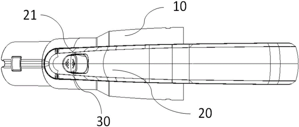
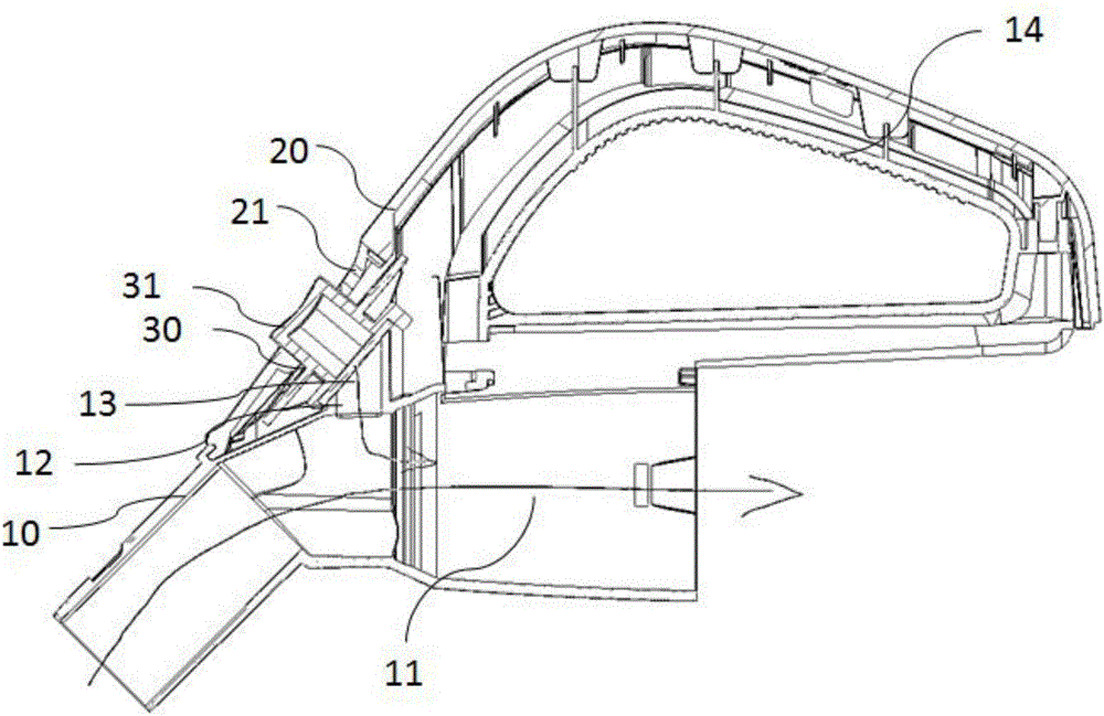
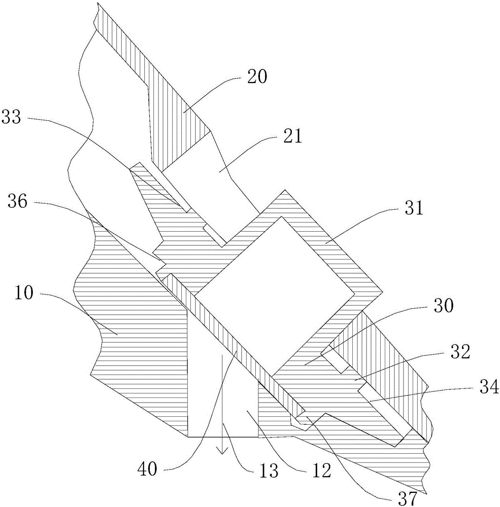
The invention provides a dust collector handle adjusting structure and a dust collector. The dust collector handle adjusting structure comprises a handle main body, a face cover and an adjusting cover, wherein a first air duct and a through hole, which communicates with the first air duct, are formed in the handle main body, and the handle is provided with a holding portion; the face cover is connected to the handle main body; the face cover is arranged in a mode of being close to the holding portion, and a notch is formed in the face cover; the adjusting cover is sandwiched between the handle main body and the face cover; the adjusting cover can slide in the notch, so that the adjusting cover has at least two working positions; in the first working position, the through hole is sealed by virtue of the adjusting cover; and in the second working position, the through hole is opened by virtue of the adjusting cover at least partially. According to the dust collector handle adjusting structure and the dust collector provided by the invention, an air quantity can be conveniently adjusted and a relatively good sealing performance can be guaranteed.

Description

technical field [0001] The invention relates to the field of vacuum cleaners, in particular to a vacuum cleaner handle adjustment structure and the vacuum cleaner. Background technique [0002] Horizontal vacuum cleaners are getting closer and closer to the lives of ordinary people, and can be seen everywhere in homes, hotels, and some entertainment halls. According to market research, the focus of current user requirements for vacuum cleaners is that the vacuum cleaner must have strong suction. However, due to different user groups, some users are more difficult to accept the problem of large push-pull force caused by large suction force due to their own strength or habits. In this way, the vacuum cleaner is required to have a function that can adjust the suction force, so as to reduce the suction force of the vacuum cleaner to absorb the ground, so as to achieve the effect of small push and pull force. In order to allow users to freely adjust the balance between suction ...

Claims


Application Information

Patent Timeline
Patent Type & Authority Applications(China)
IPC IPC(8): A47L9/32A47L9/00
CPCA47L9/0072A47L9/327
Inventor 王德旭廖泓斌曾林林陈佳兵黄月林李德智
Owner GREE ELECTRIC APPLIANCES INC
Learn More